
Content last revised on September 12, 2026
1DI400MP-050 Thermal-Electrical Optimization: Thermal Interface Material Thickness and Practical Tuning
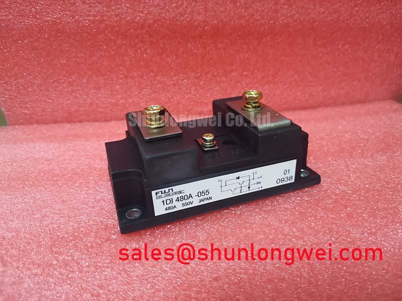
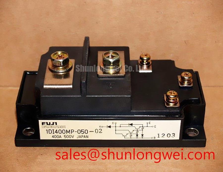
Before removing the installed device, isolate the DC link, confirm the nameplate boundary, and check the unpowered terminal network against a known-good assembly; the Fuji Electric 1DI400MP-050 is specified as a 500 V, 400 A Power Transistor Module for engineering evaluation and replacement assessment.
The baseplate interface deserves the same attention as the electrical terminals. Clean both mating surfaces, remove dried compound without scratching the metal, and inspect for burrs, contamination, or visible distortion. A thin, continuous thermal interface layer is generally preferred because excess compound can increase thermal resistance and migrate toward nearby insulation surfaces. The stated 50 to 100 µm TIM range is an Engineering Recommendation, not an official Fuji Electric rating for this model; the final thickness should be confirmed by the heatsink flatness, compound specification, and thermal test results.
When a replacement module is installed, place it on the heatsink without forcing one corner down first. Start all fasteners by hand, then tighten in a cross pattern so the baseplate settles progressively. Sequential tightening is a Design Consideration for reducing local bowing and improving contact uniformity. Designers should verify the result through thermal imaging or thermocouple measurements during a controlled load test rather than assuming that a visually complete compound imprint proves adequate cooling.
⚠️ Field Alert: Use the fastener torque specified for the actual bolt, heatsink, and assembly procedure, and disconnect the DC link before touching power or gate terminals.
For a commercial string inverter or microgrid energy storage repair, also inspect the heatsink mounting face for pressure marks left by the previous device. Such marks can reveal uneven loading that may return after replacement. The official device data supplied for this page confirms the voltage, current, and package category, but it does not establish a universal heatsink, switching frequency, or thermal resistance value; those items remain system-dependent.
Assembly Integrity and Layout Architecture: Reinforced Insulation Barrier Integrity
Verify the isolation arrangement from the circuit diagram before applying a test signal. The module’s 500 V voltage rating is an electrical device specification and should not be interpreted as a guaranteed system isolation or reinforced insulation rating. Clearance, creepage, insulating hardware, coating, pollution level, and enclosure construction must be reviewed at equipment level. Any claim involving a reinforced barrier above 5 kV or a common-mode transient immunity above 100 kV/µs requires a manufacturer or system-level source; it should not be assigned to this module without documentation.
Gate wiring should be short, physically separated from high-current commutation paths, and referenced exactly as shown in the applicable Fuji Electric documentation. Minimize the gate loop area to reduce unwanted coupling, then verify gate voltage and ringing with a suitable differential probe. A resistor, ferrite element, or damping network may be evaluated as a Typical Starting Point during bench tuning, but its value must be selected from the driver output capability, gate charge, switching speed, and measured waveform.
For top-side switching arrangements, the bootstrap capacitor is part of the driver design rather than an inherent module parameter. The integrator should account for gate charge, driver quiescent current, charging losses, refresh time, leakage, temperature, and diode reverse-recovery behavior. The selected capacitor must maintain the required gate supply throughout the intended high-side conduction interval, with the final margin verified during startup, rapid duty-cycle changes, and fault recovery.
Fuji Electric’s Power Semiconductor and IPM Modules information can be consulted when checking the appropriate family documentation and application context.
Assembly Integrity and Layout Architecture: Mitigating Hard-Switching Transients
During a suspected failure, begin with visual inspection and cold resistance checks before reconnecting the bus. Compare corresponding power terminals and gate paths with an approved reference unit, while remembering that a multimeter cannot reproduce dynamic switching stress. An abnormal reading may indicate a damaged junction, a connected snubber path, or an external circuit influence; isolate the module and verify the signal path before assigning a cause.
Short-circuit protection must be coordinated with the actual driver, current sensor, gate clamp, semiconductor fuse, and DC-link impedance. A sub-10 µs detection target and any short-circuit safe operating area limit are Design Considerations unless explicitly stated in the applicable Fuji Electric datasheet. A two-stage soft turn-off strategy can reduce the rate of current interruption, but the delay and gate profile must be validated against the module’s permitted fault conditions and the measured collector-emitter overshoot.
In the upstream rectifier section, engineers may evaluate the 7MBR10KA060 as a separate complementary circuit reference. It should not be treated as an automatic substitute or as proof of compatibility. Check voltage class, current path, gate or control requirements, thermal mounting, and protection coordination across the complete topology.
1DI400MP-050 Circuit Protection and Reliability: DC-Link Capacitance Bank Layout
Place the high-frequency DC-link capacitor connection as close as practical to the switching current loop. The design objective is to minimize parasitic inductance and suppress turn-off overshoot; the resulting peak voltage depends on the DC-link level, commutation inductance, and current slew rate. The relationship can be assessed in engineering calculation form as the DC-link voltage plus the inductive overshoot term, but the acceptable peak must be verified on the assembled inverter with an oscilloscope and an appropriately rated probe.
Symmetrical busbar geometry, short return paths, and controlled capacitor placement can improve current sharing between parallel paths. Snubber selection should consider pulse current, dielectric behavior, temperature, mounting inductance, and the measured transient spectrum. Do not assign a universal capacitance value or a fixed inductance limit to this module without the complete switching layout and operating point.
For a field replacement, inspect fuse coordination and review the semiconductor fuse I²t capability against the system’s available fault energy. This is a system protection calculation, not an official rating of the 1DI400MP-050. Gate oscillation, unexpected turn-on, or repeated fuse operation should be investigated by capturing gate-emitter and collector-emitter waveforms together, checking driver supply integrity, dead time, clamp behavior, and the condition of the surrounding snubber network.
When a neutral comparison is required, engineers can review 6MBP100TEA060-50 as a separate Fuji Electric module listing and confirm all electrical, mechanical, and control-interface requirements before any substitution decision. For gate-drive background, see Evolution of Negative Off-Bias Gate Drive Circuits; negative off-bias is a driver design option that must be evaluated against insulation, gate-emitter limits, turn-off behavior, and the controller’s fault sequence.
Additional manufacturer information is available through the Fuji Electric Power Semiconductors Portal.