Content last revised on September 25, 2026
SKD 62/16 Operational Boundaries: Evaluating Commutation Turn-Off Voltage Limits
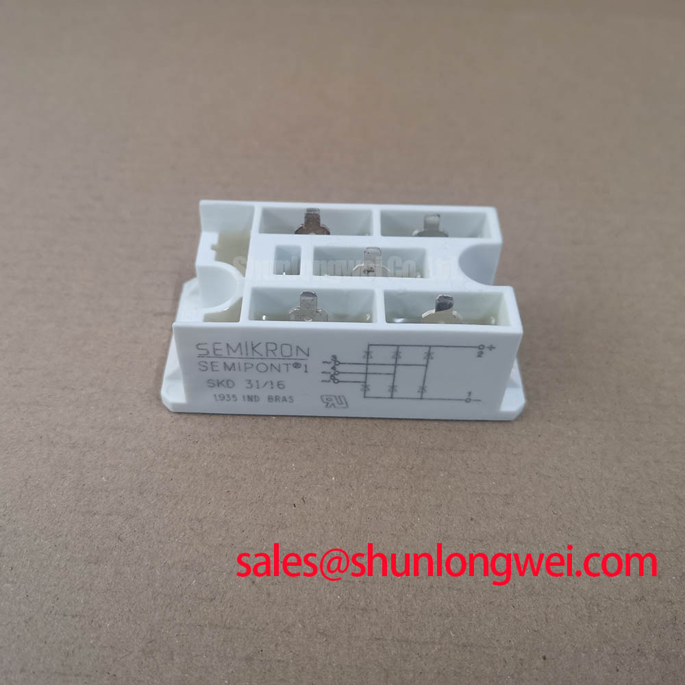
Before installing a replacement, isolate the assembly and verify the original nameplate, terminal markings, mechanical footprint, and cold-state resistance path against the removed device. The Semikron SKD 62/16 is specified in the supplied product data as a Bridge Rectifier Module with a rated voltage of 1600 V, a rated current of 62 A, and a Semipont housing.
These values define the primary product identity, but they do not by themselves establish suitability for every grid-tied static Var compensator or thyristor-switched capacitor assembly. The system engineer should confirm the rectifier position in the original schematic, the applied AC waveform, the conduction sequence, and the available thermal path. When a controlled or phase-angle circuit changes its conduction angle, line current distortion and commutation behavior remain system-level subjects requiring measurement at the installed terminals.
For a repair assessment, inspect the busbar and cable terminations for discoloration, loose hardware, surface tracking, and signs of uneven pressure. Confirm that each power connection is clean and mechanically stable before applying an insulation or powered test. A cold ohmmeter check can help compare the suspect unit with a known-good path, but a resistance reading is only a screening observation and should not be treated as proof of semiconductor health.
Reverse-recovery current and recovery time are important when a diode bridge operates alongside switching devices. The available information supplied for this product page does not provide verified IRRM, trr, soft-recovery classification, or commutation peak limits. Those values must be taken from the applicable Semikron technical documentation before calculating switching loss, selecting an RC network, or judging EMI behavior. Engineers comparing a higher-current reference may review SKD82/18, while retaining full responsibility for voltage, current, terminal, thermal, and mechanical compatibility.
During an energized validation, use an appropriately rated differential probe and current measurement method to observe the commutation interval. Check peak voltage at the module terminals, not only at a remote DC-link point, because wiring inductance and busbar geometry can change the local stress. The Semikron-Danfoss Power Electronics and Modules Official Hub is a suitable manufacturer information source for confirming current documentation.
SKD 62/16 Circuit Protection and Reliability: AC Input Transient Overvoltage
In a static Var compensator or thyristor-switched capacitor panel, the rectifier section should be reviewed together with the AC input protection, switching devices, fuses, busbars, and grounding arrangement. A metal oxide varistor or RC snubber can be considered as part of the system protection network, but its voltage class, energy capability, coordination, and physical placement must be selected from the measured supply conditions and the complete protection study.
The supplied product data confirms the SKD 62/16 voltage rating as 1600 V. It does not provide a verified MOV selection, snubber capacitance, surge current profile, IEEE 61000-4-5 test result, or repetitive transient limit. Those items should not be inferred from the model number. The design team should verify the actual line-to-line and line-to-earth transient environment, the upstream protection, and the required insulation coordination before approving a field replacement.
Transient protection is most effective when the current path is short, mechanically secure, and arranged to limit unwanted loop inductance. Keep protective components physically associated with the power path they protect, while maintaining the required clearance and creepage distances. Do not route sensitive gate or measurement wiring through the high-current commutation loop. If an auxiliary emitter or sensing connection exists in the wider assembly, follow the original schematic and keep its return path separate from high di/dt power conductors.
After a surge event, inspect more than the visible module body. Check fuse condition, busbar joints, capacitor terminals, snubber components, PCB tracks, and protective earth connections. A visually intact module can still require electrical comparison with a known-good unit. Record the measured fault location and test conditions rather than assigning a single cause from one resistance or continuity reading.
The related SKD 25/14 may appear elsewhere in a compatible power-conversion topology, but it should be treated as a separate component requiring its own verified ratings and connection review. Product family resemblance is not a substitute for a circuit-specific compatibility check.
SKD 62/16 Circuit Protection and Reliability: ITSM Assessment
Short-duration overload assessment requires the original technical sheet for the exact device revision. The supplied parameters establish 1600 V, 62 A, and Semipont construction, but they do not include a verified ITSM value, 10 ms half-cycle surge rating, junction-temperature curve, thermal resistance, or recovery specification. Those missing values are essential before a designer can evaluate a repetitive capacitor-switching disturbance or an AC fault current.
For field troubleshooting, begin with the event record: phase angle at the time of failure, upstream fuse status, capacitor bank condition, thyristor command timing, and whether reverse voltage was reapplied after an abnormal conduction event. Compare all three phases where the topology permits. Unequal current, an unexpected fuse operation, or irregular waveform shape may indicate a problem in the surrounding circuit, but none of these observations independently proves that the SKD 62/16 is the initiating failure.
Thermal verification should include the mounting surface, interface material, clamping condition, airflow or heatsink arrangement, and the actual duty cycle. The current rating printed in a product listing should not be converted into a guaranteed continuous operating current without the manufacturer’s specified case or junction conditions. A repair engineer should confirm the original cooling arrangement and repeat the relevant temperature and waveform checks after replacement.
Phase-controlled operation also affects harmonics. Changing the conduction angle can alter line current shape and may increase filtering or power-quality requirements at the system level. Engineers should measure current distortion at the point required by the installation specification and verify that the selected protection does not create a new resonance with the capacitor bank. The SKD 62/16 page provides the component identity and stated ratings; it does not certify the complete SVC installation for EMC or power-quality compliance.
Field Alert: Follow the original fastener specification and approved interface-material procedure, because uneven mounting pressure can compromise heat transfer even when the electrical connections appear correct.
Preventing Spurious Faults: Type 2 Coordination and Dead-Short Review
A semiconductor fuse study should compare the fuse clearing energy with the rectifier’s verified surge withstand and thermal limits. The applicable fuse I2t coordination table is not included in the supplied product parameters, and no unsupported fuse rating should be presented as a guaranteed match for the SKD 62/16. Obtain the exact manufacturer curve or coordination guidance for the device revision and the selected fuse family before releasing the protection design.
For a suspected dead short, isolate the supply, discharge stored energy according to the equipment procedure, and document the condition of every protection stage before removing the module. Inspect semiconductor fuses, busbar insulation, capacitor terminals, contactors, thyristor stacks, and gate-control wiring. A cleared fuse may be the result of a downstream fault, an abnormal switching sequence, or an overvoltage event; the fuse condition alone does not identify the failed component.
Type 2 coordination is a system design objective rather than an inherent claim of the bridge module. The engineer should verify that the protective device clears within the withstand envelope of the rectifier and associated switching elements, while also checking prospective short-circuit current, fault loop impedance, enclosure containment, and restart behavior. Any claim that a particular arrangement prevents physical damage requires documented coordination data and testing for the actual assembly.
After replacement, use a controlled recommissioning sequence. Confirm terminal polarity and phase identification, check insulation according to the equipment procedure, and verify that command signals remain inhibited until the DC link and protection circuits have been assessed. Apply power under a test plan that records input current, terminal voltage, heatsink temperature, and switching behavior. For broader component-selection context, the engineering discussion at Future of Power Electronics can be reviewed alongside the device-specific documentation.
The Semikron MiniSKiiP power module reference is relevant only when the equipment design calls for that separate product line. It should not be used to infer the SKD 62/16 terminal layout, thermal data, surge capability, or protection limits. Confirm every replacement detail against the original schematic, the applicable Semikron documentation, and measurements from the installed system.