Content last revised on September 18, 2026
Transient Dynamics & Electrical Design: AC to DC Transfer Conditions with SKD 31F/16
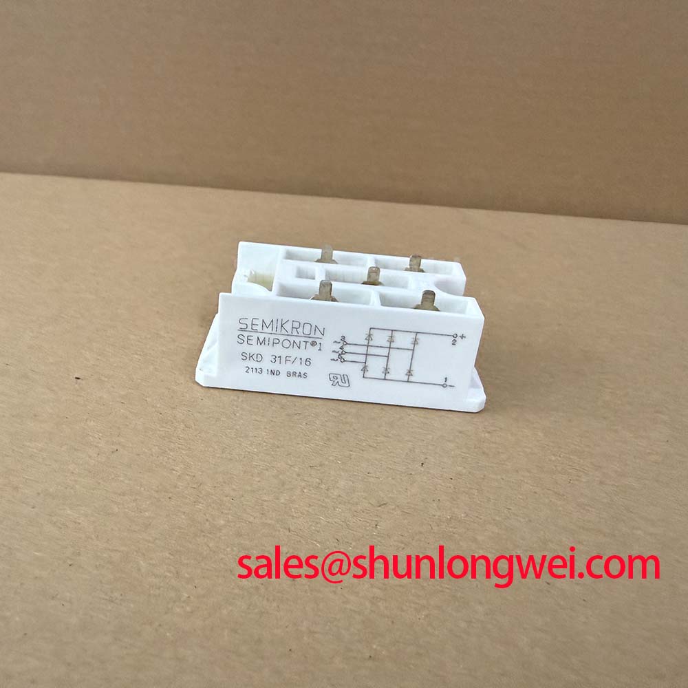
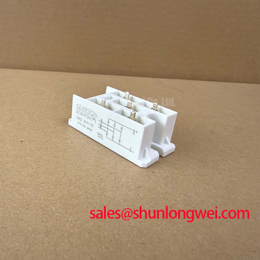
In a three phase motor solid state soft starter, a bridge rectifier can appear in an auxiliary DC supply, control supply, excitation circuit, or measurement related power section. The SKD 31F/16 should be assessed as an uncontrolled diode bridge. It does not provide firing angle control. Any delay angle adjustment in a soft starter is performed by the separate thyristor control stage, its firing board, and the associated synchronization circuitry rather than by this rectifier module.
This distinction matters during troubleshooting. If a technician observes an abnormal DC bus waveform while the firing angle is being changed, the investigation should separate the diode bridge from the controlled rectifier or SCR power path. Verify phase input presence, DC output polarity, gate drive timing at the separately controlled devices, and the condition of the load circuit. A missing phase, a degraded contactor connection, or an incorrect control reference can create symptoms that resemble a bridge failure.
The 1600 V VRRM rating is the official repetitive reverse voltage boundary for the SKD 31F/16. It is relevant when evaluating line transients, commutation events, and system overvoltage protection. It does not establish a complete surge immunity classification for the finished starter. Design Consideration: maintain short, direct connections between the AC input conductors, rectifier terminals, surge suppression network, and DC capacitance where present, because conductor inductance can add transient voltage during commutation.
At 31 A at Tc = 85°C, the output current rating is tied to the stated case temperature. A cabinet temperature reading alone is not a substitute for confirming case temperature, heat sink condition, airflow, and thermal interface condition. Where the existing unit is being replaced, technicians should preserve the original conductor routing and terminal assignment rather than infer terminal functions from a different rectifier family.
In repair documentation, record the rectifier terminal connections before removal and compare them with the original schematic. This is especially important where a service board contains both AC inputs and DC outputs in close proximity. For related low current rectification positions in a wider assembly, the SKD 25/14 is a separate bridge rectifier module that may be evaluated against the actual circuit requirements. It should not be treated as an automatic substitute for the SKD 31F/16 because electrical ratings, thermal conditions, package fit, and wiring layout must all be verified by the responsible engineer.
Field Diagnostics & Commissioning: Fuse Total Clearing I²t versus Device Stress in SKD 31F/16 Topologies
De energize the cabinet, verify the DC link has discharged through the equipment’s intended procedure, and isolate external energy sources before testing the bridge circuit. With the module disconnected as required by the service procedure, compare each diode path using an appropriate diode test method and compare findings with the known circuit diagram. A simple resistance reading may be influenced by capacitors, snubbers, parallel suppressors, or connected control electronics, so it should not be used as a stand alone verdict on module condition.
The supplied official ratings include 370 A IFSM for 10 ms at 25°C, but they do not provide a semiconductor fuse coordination table, a device I²t value, or fuse total clearing I²t limits for this product page. Those missing values must not be calculated or assumed from the surge current rating alone. Fuse selection is a Design Consideration requiring the fuse manufacturer’s time current and total clearing I²t documentation, the available fault current at the installation, the source impedance, and the equipment protection study.
A fuse may open after a destructive energy event has already reached a semiconductor if its clearing behavior is not coordinated with the actual circuit. Conversely, a fuse selected without considering routine charging current or expected transient conditions can create nuisance trips. During commissioning, inspect the fuse holder contact pressure, busbar joints, cable lugs, and signs of localized heating. Measure voltage drop across suspect joints under controlled operating conditions rather than relying on visual inspection alone.
⚠️ Maintenance Note: Regularly monitor terminal and heat sink contact temperature rise while checking that cabinet filters and cooling paths remain free of accumulated dust.
The official 2500 V AC isolation voltage is relevant to the separation between the module’s electrical circuit and its mounting arrangement under the specified factory rating. It does not replace the isolation coordination requirements of the entire starter, including creepage, clearance, enclosure bonding, cable gland selection, and test procedures. The system integrator should verify the original insulation coordination requirements before applying an external withstand test to a repaired cabinet.
SKD 31F/16 Thermal Electrical Optimization: Industrial Surge Immunity Practical Tuning
Industrial surge immunity for a complete machine is normally evaluated at system level. IEC 61000-4-5 is the commonly referenced surge immunity standard; the individual SKD 31F/16 module should not be presented as independently certified to that system standard. Its official 1600 V VRRM rating provides an electrical limit for repetitive reverse voltage, while the final surge response depends on the incoming supply, switching topology, wiring length, suppression parts, grounding strategy, and test configuration.
When reviewing an existing MOV and RC suppression network, first identify its actual location. An MOV across the AC input can clamp line borne events before they reach the bridge, while an RC network across a switching path can address ringing caused by circuit inductance and changing current. These functions are related but not interchangeable. Engineering Recommendation: inspect MOVs for cracking, discoloration, or evidence of thermal stress and verify their specification against the original equipment design. Do not select a replacement clamping level from the SKD 31F/16 voltage rating alone.
Soft starter control boards often use optocouplers or digital isolators to separate low voltage control references from power circuit noise. Design Consideration: preserve physical separation between power conductors and sensitive control wiring, and verify common mode transient behavior using measurements at the actual installed drive board. Unexpected firing behavior can be associated with several factors, including control supply disturbance, grounding impedance, synchronization errors, or coupling from high current conductors. Oscilloscope checks should be made against a known good signal path and with measurement equipment suitable for the circuit’s voltage environment.
For the SKD 31F/16 mounting interface, no official mounting torque value has been supplied here. The responsible technician should use the module documentation, equipment manufacturer service data, and the applicable fastener specification rather than applying a generic torque value. Clean the heat sink surface, inspect for flatness concerns or old hardened interface material, and apply the original approved thermal interface method consistently. A loose mounting condition can raise thermal resistance, while excessive mechanical force can damage the package or mounting hardware.
For manufacturer level product family information and technical context, consult the Semikron Danfoss Power Electronics and Modules official hub. The original equipment schematic and product documentation remain the controlling references for service decisions.
SKD 31F/16 Circuit Protection & Reliability: Diode Reverse Recovery and Commutation Checks
Reverse recovery behavior affects how a diode bridge interacts with source inductance, downstream capacitance, and nearby controlled semiconductor stages. However, no official values for reverse recovery peak current, reverse recovery time, or softness characteristics have been provided for the SKD 31F/16 in the available specification set. It would therefore be inaccurate to assign numerical reverse recovery performance or to claim a particular EMI result for this model.
In field work, look instead at the measurable assembly behavior. A ringing waveform, fuse stress, elevated thermal readings, or interference on firing signals may indicate a need to inspect commutation loops, suppression components, connector integrity, and layout changes made during prior repairs. These observations do not establish one single cause. Verify voltage and current waveforms with suitable isolated measurement methods, then compare the result with the original equipment performance requirements.
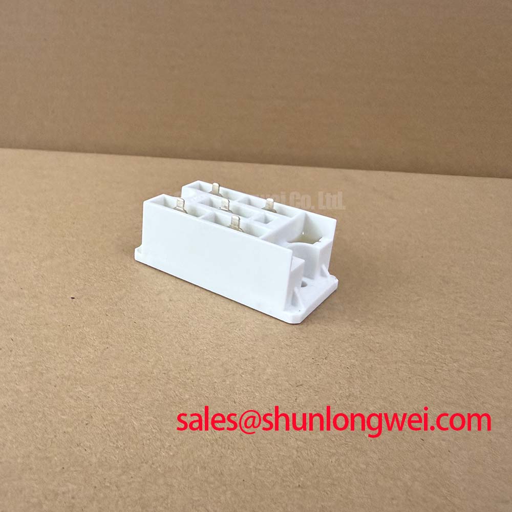
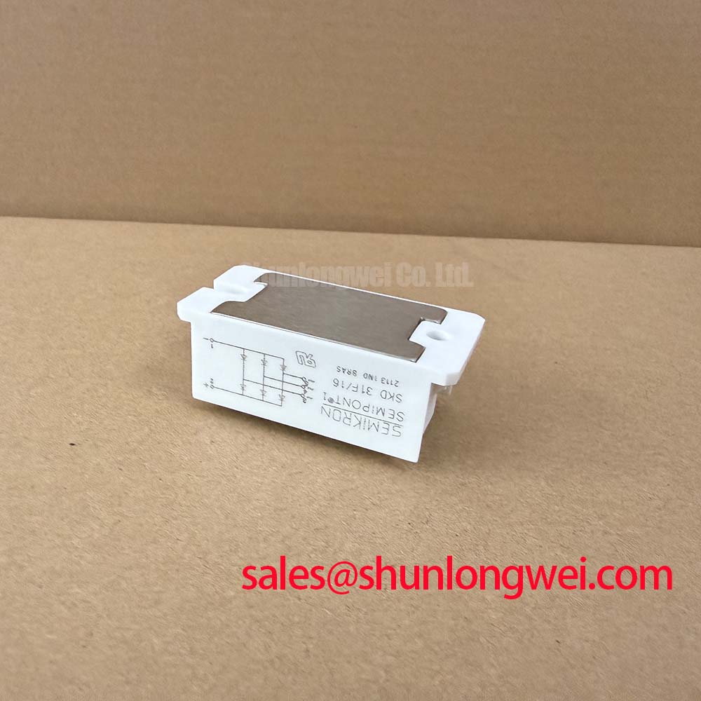
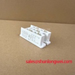
The SEMIPONT 1 housing supports compact installation, but compactness makes mechanical discipline important. Check that the module sits evenly on its heat sink, that terminal hardware is secure, and that no cable strain is transferred into the package terminals. Where disc spring hardware is used in the original assembly, retain its intended arrangement and inspect it for corrosion, loss of alignment, or incorrect reassembly. Spring hardware is part of the clamping system and should not be changed without confirmation from the machine documentation.
For preventive maintenance, examine cooling airflow, cabinet sealing, moisture exposure, and condensation risk during seasonal temperature changes. Contamination on heat sinks can reduce heat transfer, while moisture and residue around terminals can alter surface leakage behavior. Use the equipment’s approved cleaning and inspection procedures, then confirm electrical connections before returning the starter to operation.
Engineers comparing power conversion behavior in appliance related resonant systems can review Resonant Topologies in Home Appliances for topology context. That material is not a substitute for the circuit specific protection and commissioning checks required for a three phase motor soft starter. If a higher current Semikron bridge is being assessed during a documented redesign, the SKD82/18 is a separately rated module for objective engineering comparison against the original electrical, thermal, and mechanical requirements.