Content last revised on September 15, 2026
SKD160/12 Thermal Electrical Optimization: Thermal Interface Material Spreading across Practical Tuning
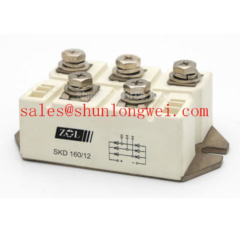
Begin the incoming inspection by checking the part marking, case condition, terminal condition, and the original circuit documentation before applying power; the Semikron SKD160/12 is a high current bridge rectifier module with an official repetitive peak reverse voltage of 1200 V and a maximum average forward current of 160 A at Tc = 100°C.
Its official electrical data also lists a 1500 A peak forward surge current for 10 ms, a typical specified forward voltage drop of 1.45 V at If = 150 A, and an isolation voltage of 3000 V AC for 1 minute. The case style is identified as SEMIPONT 4, G 55. These values provide the starting point for a replacement assessment, but they do not replace verification of the complete rectifier assembly, fuse coordination, cooling system, switching waveform, and operating duty.
For a medium frequency induction melting or metal hardening power supply, the module is evaluated in the rectifier section that supplies the downstream DC link or controlled power conversion stage. A repair engineer should compare the original bridge configuration, phase connections, current path, and protective components before installation. The system integrator should verify the required voltage, current waveform, commutation conditions, and cooling method from the original equipment documentation.
The forward voltage specification is especially relevant when estimating heat generation in the conducting path. Actual dissipation depends on conduction angle, current waveform, temperature, parallel device behavior, and the complete circuit topology. The official 1.45 V value at 150 A should therefore be treated as a datasheet reference point rather than a complete thermal design result. Designers should evaluate the worst case current and temperature in the assembled furnace power unit, then confirm junction and case conditions through measurement.
The copper baseplate and heatsink interface require careful preparation. Remove residue from both surfaces, inspect for burrs or raised areas, and confirm that the heatsink is sufficiently flat for the module footprint. Apply thermal interface material as a thin, continuous film that covers the effective contact area without creating large voids. Excess compound can reduce mechanical stability and contaminate nearby insulation surfaces, while insufficient coverage can leave local air gaps.
Mounting pressure should be introduced progressively and evenly across the fixing points. The correct bolt size, washer arrangement, tightening sequence, and torque value must be taken from the applicable Semikron mechanical documentation for this exact case style. The supplied information does not establish a model specific mounting torque, so a generic torque value should not be presented as an official SKD160/12 parameter. After tightening, inspect the module for distortion and confirm that the baseplate remains seated without rocking.
Terminal connections should be clean, mechanically supported, and routed to limit unnecessary loop area. Confirm the terminal identification against the original schematic rather than relying on physical position alone. High current conductors should not transfer cable or busbar strain into the module terminals. After assembly, check the mechanical security of each connection and inspect the insulation clearance around the DC and AC conductors.
| Official characteristic | Symbol | Value |
|---|---|---|
| Repetitive peak reverse voltage | VRRM | 1200 V |
| Maximum average forward current at Tc = 100°C | ID | 160 A |
| Peak forward surge current for 10 ms | IFSM | 1500 A |
| Forward voltage drop at If = 150 A | VF | 1.45 V |
| Isolation voltage for 1 minute AC test | Visol | 3000 V AC |
| Case style | SEMIPONT 4, G 55 |
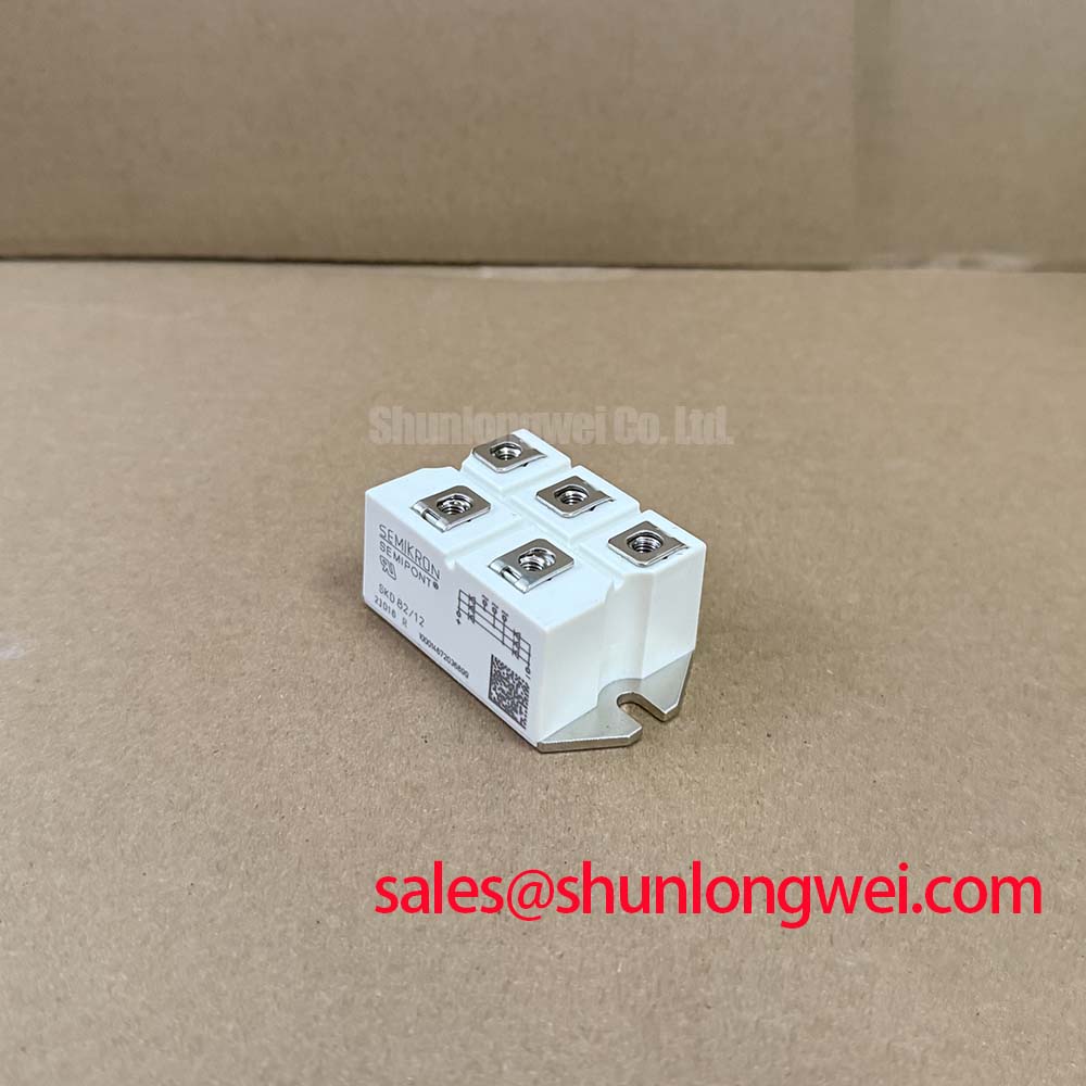
When a rectifier replacement is being considered for a lower power branch or a different current class, the SKD82/18 can be reviewed as a separate Semikron family option. This is an engineering comparison only; voltage class, current duty, thermal resistance, mechanical fit, terminal arrangement, and protection coordination must be checked before any substitution.
SKD160/12 Circuit Protection and Reliability: Calibrating Rectifier Protection for Induction Power Supplies
The SKD160/12 is a bridge rectifier module, not a gated thyristor or IGBT switching device. It does not provide a gate terminal, gate firing pulse, gate holding current, or Miller plateau control. Those functions belong to other parts of a controlled converter, such as thyristor assemblies, IGBT modules, or an external switching stage. This distinction matters when diagnosing a medium frequency induction furnace that contains both an input rectifier and a downstream inverter.
For the rectifier itself, protection begins with the relationship between the AC source, transformer impedance, line inductance, fuses, contactors, and the module’s surge capability. The official IFSM rating is 1500 A for 10 ms, but that value does not authorize repeated surge operation or define a complete fuse selection. Fuse coordination requires the manufacturer’s time current curves, prospective fault current, clearing time, and the applicable I2t data for the selected semiconductor fuse. Because no fuse I2t coordination table is provided here, the correct fuse rating must be verified from the equipment protection study and the relevant technical documentation.
A service engineer should record the original fuse class, voltage rating, interrupting capability, and physical arrangement before replacement. Check whether the fuse protects individual AC legs, the DC output, or a transformer secondary. A fuse that physically fits may still have unsuitable clearing behavior or energy coordination. The rectifier’s surge rating should be assessed together with transformer inrush and capacitor charging current, especially where a large DC link follows the bridge.
In regenerative braking or high power resistor energy absorption systems, the rectifier may feed a common DC link that also supplies a braking chopper. The braking resistor and chopper absorb energy according to the system control strategy; the SKD160/12 itself remains the rectifying element and should not be described as the energy absorbing switch. Designers should verify DC link precharge, braking chopper timing, overvoltage detection, and fault isolation so that abnormal regenerative energy does not impose an uncontrolled condition on the input bridge.
Parallel rectifier paths require particular attention to static and dynamic current sharing. Positive temperature behavior in semiconductor conduction can support sharing in some arrangements, but equal sharing cannot be assumed from device matching alone. Busbar resistance, inductance, conductor length, thermal coupling, diode forward characteristics, and mounting pressure all influence current distribution. Use a symmetrical physical layout where parallel paths are required, then validate branch currents under the actual load waveform.
Localized heating should be investigated through measured temperature distribution, terminal voltage drop, current balance, and the condition of the heatsink interface. A single warm terminal may reflect connection resistance, unequal busbar geometry, cooling nonuniformity, or an upstream commutation issue. Verify the complete path with appropriate insulated measurement equipment rather than assigning the symptom to the module alone.
The official isolation rating of 3000 V AC for 1 minute is an isolation test specification, not a blanket statement that the entire furnace power cabinet is safe at that voltage. The finished assembly still requires appropriate creepage, clearance, barriers, grounding, insulation coordination, and service procedures. The Semikron-Danfoss Power Electronics and Modules Official Hub is a suitable manufacturer resource for confirming current technical documentation and application information.
SKD160/12 Circuit Protection and Reliability: Calibrating Snubber and Commutation Networks
In a bridge rectifier feeding an inductive industrial load, parasitic inductance and line commutation can produce voltage transients at diode turn off. An RC snubber, surge suppressor, or series reactor may be part of the original equipment design, but the values of Rs, Cs, and any saturable reactor are system determined. They should not be copied from an unrelated module or presented as fixed SKD160/12 specifications.
The practical task is to identify the actual transient at the module terminals. Use a properly rated differential probe and a measurement setup with a controlled connection loop. Compare the observed peak voltage and ringing frequency with the bridge voltage environment, transformer leakage, wiring inductance, and the protective component ratings. The goal is to suppress excessive overshoot and unwanted commutation stress while avoiding a snubber that creates unacceptable reactive current or resistor heating.
Snubber components should be placed according to the current loop they are intended to control. A physically remote network may show an acceptable bench reading while leaving the module terminals exposed to a different transient in the installed cabinet. Keep the high current AC and DC paths short and balanced, and verify the result during startup, steady operation, load changes, and fault interruption.
For a medium frequency induction melting and hardening furnace, the bridge is often exposed to a demanding combination of transformer current, pulsed DC link demand, inverter modulation, and rapid load variation. A rectifier snubber cannot correct every problem created by the downstream inverter. If the waveform shows excessive ringing after the bridge, inspect the transformer connection, busbar geometry, DC link capacitor arrangement, inverter commutation path, and fault control sequence as a complete system.
Protection components must also be checked for their own operating stress. The voltage rating of the capacitor, pulse capability of the resistor, repetitive energy, temperature rise, and insulation distance should be verified under the actual waveform. Designers should confirm the selected network through oscilloscope testing and thermal observation rather than relying on nominal calculations alone.
Where the equipment uses a separate controlled rectifier or auxiliary input stage, the SKD 25/14 may appear as a related component in the wider power topology. Its presence does not establish electrical interchangeability with the SKD160/12. Confirm the required bridge configuration, voltage class, current rating, case style, terminal arrangement, and cooling interface from the original equipment records.
💡 Pro Tip: De-energize the cabinet and verify the DC link has discharged before touching the bridge terminals, because a rectifier replacement procedure must account for stored energy outside the module.
Assembly Integrity and Layout Architecture: Implementing AC Input Transient Clamping for SKD160/12
AC input protection for the SKD160/12 should be designed around the complete supply path rather than the bridge rating alone. The official 1200 V VRRM value describes repetitive reverse voltage capability under specified conditions; it does not define the permissible peak of an uncoordinated utility surge. The system engineer should evaluate transformer impedance, incoming protection, earthing, cabinet wiring, and the surge environment before selecting a metal oxide varistor or another clamping stage.
Where an installation is assessed against an immunity test such as IEC 61000-4-5, the test level, coupling method, source impedance, and equipment category must be established for the finished assembly. A discrete rectifier module cannot independently claim compliance with the EMC or immunity performance of the complete furnace power cabinet. MOV selection should consider continuous operating voltage, clamping behavior, energy rating, repetitive surge exposure, fusing, and end of life containment according to the system safety design.
An input MOV may be coordinated with an upstream fuse and an RC network across the relevant AC path. The physical placement should minimize the protected loop while maintaining the required insulation distance. Do not place a protection component where its failure can bridge an insulation barrier or expose service personnel to an uncontained fault. The selected parts and enclosure must be reviewed under normal operation, abnormal overvoltage, and service conditions.
Inspection after installation should include torque verification against the applicable mechanical document, confirmation that no washer or busbar is contacting an unintended terminal, and a check that the heatsink remains electrically isolated where the design requires it. Apply hipot or insulation testing only with the module, capacitors, control electronics, and surge components connected or disconnected according to the equipment manufacturer’s approved procedure. The SKD160/12 isolation specification alone does not define the test method for the finished power converter.
For high current rectifier assemblies, layout symmetry is useful when it reduces unequal conductor impedance and circulating stress. This is a Design Consideration, not a guaranteed performance characteristic of the module. During commissioning, measure phase current balance, bridge terminal waveform, heatsink temperature, DC link ripple, and the response of the protective devices. If the furnace uses regenerative braking, include the braking chopper and resistor bank in the fault review so that an overvoltage event is not incorrectly attributed to the input bridge.
For broader maintenance reference involving industrial power electronics testing and adjacent display based control equipment, engineers may consult The Ultimate Guide to Industrial TFT LCD Technology. The guide is a general engineering resource and does not replace the Semikron documentation for the SKD160/12.
Before releasing the repaired unit, compare the installed module with the original electrical and mechanical records, confirm the 160 A at Tc = 100°C rating is suitable for the measured duty, verify the protective coordination, and perform controlled energization with the cabinet interlocks and discharge procedure active.