

Content last revised on October 1, 2026
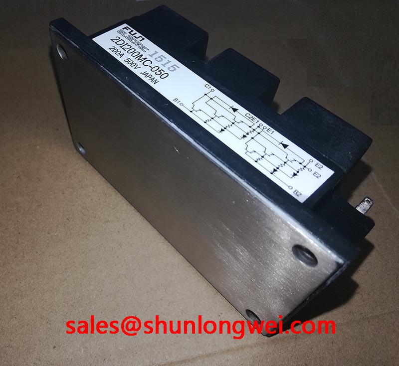
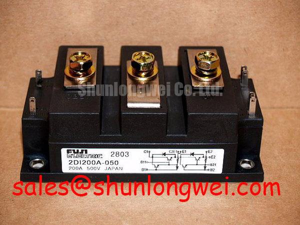
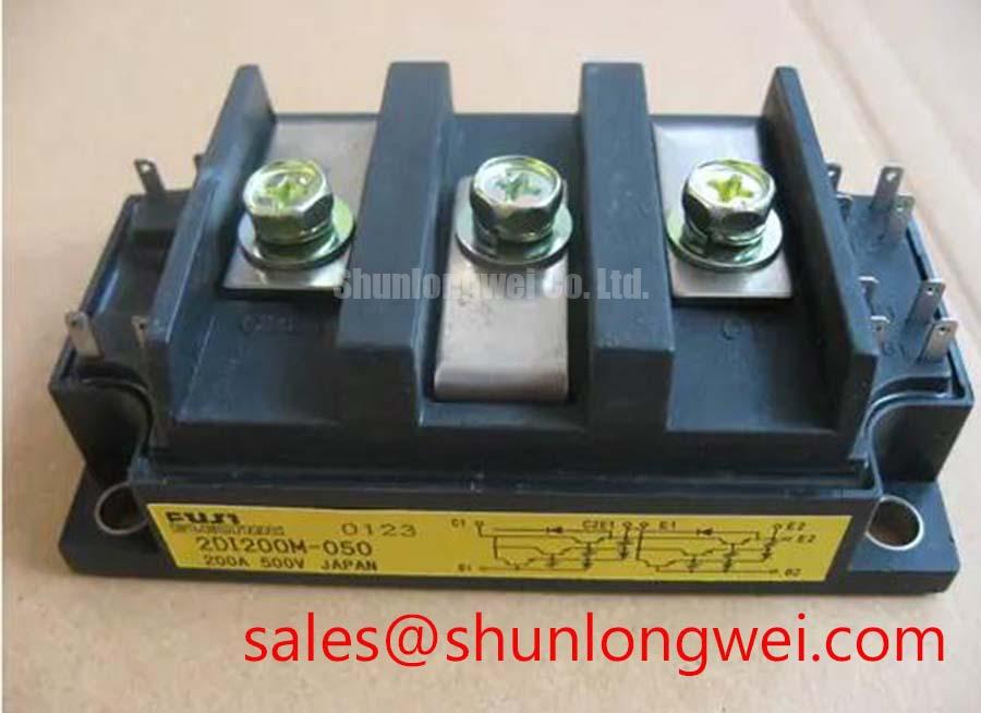
Assembly Integrity & Layout Architecture for 2DI200M-050
| Manufacturer | Fuji Electric |
|---|---|
| Model | 2DI200M-050 |
| Product category | Diode Module |
| Package | Power Diode Bridge Module |
| Rated voltage | 500.0 V Official Specification |
| Rated current | 200.0 A Official Specification |
Measure the cold-state resistance path between the module terminals and compare each reading with an electrically known-good unit before applying power; a strongly inconsistent result can indicate a connection problem, parallel circuit influence, or internal damage that requires isolation testing.
The 2DI200M-050 is identified by Fuji Electric as a Power Diode Bridge Module with a 500.0 V rated voltage and 200.0 A rated current. These are Official Specification values for component identification and electrical boundary checks. They do not, by themselves, establish the allowable current in every induction heating duty cycle. The system designer should evaluate conduction duration, cooling conditions, commutation behavior, line impedance, and repetitive surge exposure together.
For a medium-frequency induction melting or hardening furnace, inspect the copper baseplate and heatsink contact pattern after assembly. The contact surface should remain mechanically stable without rocking, localized lift, or visible distortion. Apply thermal interface material as a thin, even layer selected for the actual surface finish and thermal resistance target. Thermal performance depends on the complete path from junction to case, interface, heatsink, and cooling system; the module rating cannot replace a measured thermal verification.
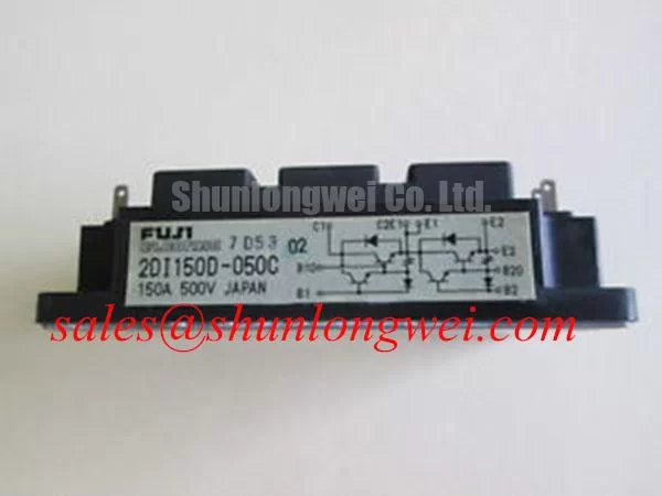
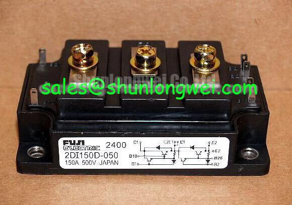
Use the original Fuji Electric mechanical documentation to confirm terminal identification, tightening torque, fuse coordination data, and any case-to-heatsink requirements. Do not transfer torque values from another package family. During commissioning, check that busbar forces are not carried by the power terminals and that the current path remains symmetrical. The related 2DI150MA-050 may be reviewed as a separate reference model, but its electrical and mechanical data must be evaluated independently.
Field Diagnostics & Commissioning: Surge Protection
Capture the AC input and bridge-terminal waveforms during energization and switching, then inspect abnormal overshoot, ringing, and unequal phase behavior against the known-good signal path before changing protection components.
The bridge should be evaluated within the complete protection network used by the furnace, including primary spark gaps, MOVs, semiconductor fuses, wiring inductance, and any RC suppression stage. IEC 61000-4-5 test conditions can be useful for system-level surge assessment, but they do not constitute an automatic rating for this diode module. MOV selection must account for the actual line voltage, temporary overvoltage, surge current, energy absorption, coordination with upstream protection, and the voltage that reaches the diode bridge.
An RC network placed ahead of a thyristor or rectifier stage can alter dv/dt, ringing, and leakage behavior. Its suitability should be established through measured waveforms and thermal observation rather than by assuming that a generic capacitor and resistor combination will protect every topology. A diode bridge connected to a high-energy induction power supply also requires attention to cable routing and loop area, since parasitic inductance can increase transient voltage at the semiconductor terminals.
Fuji Electric’s Global Power Semiconductor Technologies resources provide broader manufacturer context, while the Fuji Electric PIM 7-Pack page concerns a different product family and should not be treated as a direct specification source for this diode bridge.
Field Diagnostics & Commissioning: I2t Fuse Coordination
Inspect the semiconductor fuse, fuse holder, busbar joints, and bridge terminals after a fault event, then compare the fuse’s published clearing I2t with the diode module’s applicable withstand data from the original technical documentation.
I2t coordination is a system calculation, not a substitute for the 500.0 V voltage rating or 200.0 A current rating. The engineer must use the prospective short-circuit current, fuse pre-arcing and clearing characteristics, source impedance, DC-link or AC-line configuration, and fault duration. The comparison should cover both the fuse clearing energy and the semiconductor’s permitted surge or short-time stress under the relevant temperature and recovery conditions.
For dead-short protection, examine the physical evidence after interruption: cracked fuse bodies, carbonized insulation, displaced terminals, copper vapor deposition, and marks around the module baseplate. These observations help distinguish a protection-coordination issue from a loose connection, excessive commutation inductance, or a pre-existing cooling problem. No field failure rate or guaranteed damage threshold should be assigned without controlled test data and a documented source.
Bench Diagnostic: Isolate and discharge the furnace power stage before disconnecting any bridge terminal, because stored energy and parallel paths can invalidate resistance measurements and create an electrical hazard.
Benchtop Waveform Tuning: ITSM Safety Derating
Record the current waveform through the bridge during startup, overload recovery, and repeated line disturbances, then compare each measured peak and repetition pattern with the manufacturer’s ITSM, I2t, reverse-voltage, and thermal specifications.
The 10 ms half-cycle surge convention is relevant when reviewing a sinusoidal non-repetitive surge rating, but it must not be treated as permission for repeated furnace current pulses. Repetitive operation changes junction heating, recovery behavior, and available thermal margin. Designers should determine the actual junction temperature from the complete cooling path and verify that reverse voltage is reapplied only within the documented operating boundary.
Waveform tuning should focus on reducing unnecessary ringing and controlling the commutation loop. Review diode reverse-recovery softness, transformer leakage, busbar symmetry, and the interaction between the bridge and any thyristor or switching stage. The The 1200 V CoolSiC™ MOSFET Advantage in Three article can provide broader switching-topology context, but it does not change the official ratings of the 2DI200M-050.
For repair qualification, record the applied line condition, cooling state, measured terminal waveform, fuse arrangement, and thermal response. The final acceptance decision should be based on the original Fuji Electric data for this model and measured system margins under the intended induction heating duty.