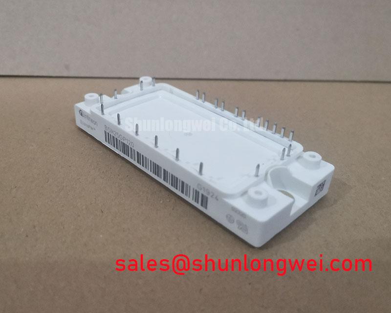


Infineon BSM25GP120 | A Workhorse IGBT for Robust Power Conversion
The Infineon BSM25GP120 isn't the newest IGBT module on the block, and that is precisely its strength. For design engineers working on systems where proven reliability, thermal stability, and cost-effectiveness are paramount, this module remains a go-to component. It’s a classic workhorse, engineered for longevity in demanding, low-to-medium frequency power applications.
Core Strengths of the BSM25GP120
- Proven Field Reliability: Built on mature Trench and Field-Stop IGBT technology, this module has a long track record of dependable performance in industrial environments.
- Optimized for Low Frequency: Its electrical characteristics are tailored for applications operating below 20 kHz, prioritizing low conduction losses over ultra-fast switching speeds.
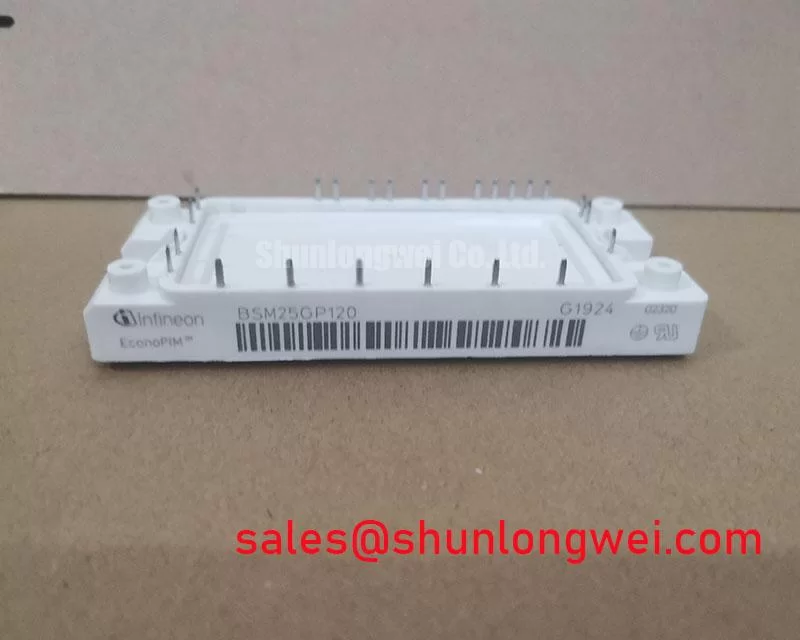
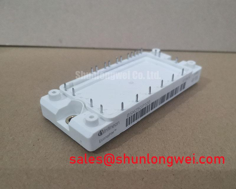
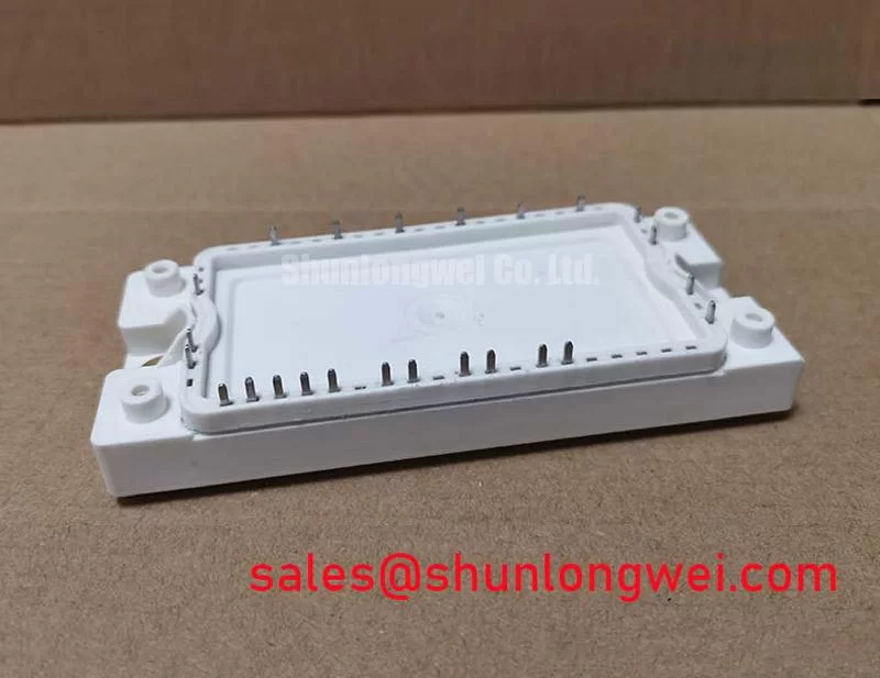
- Robust Packaging: Housed in a standard industrial package, it offers excellent thermal performance and mechanical robustness, simplifying heatsink mounting and system assembly.
- Integrated Solution: As a dual or half-bridge module, it integrates two IGBTs with corresponding freewheeling diodes, reducing component count and simplifying PCB layout compared to discrete solutions.
Application Scenarios & Engineering Value
Understanding where the BSM25GP120 excels is key to leveraging its value. It's not designed for high-frequency EV inverters, but for the backbone of industrial automation.
- Standard Motor Drives: For general-purpose Variable Frequency Drives (VFDs) up to ~11 kW, the BSM25GP120 provides the ideal balance of performance and cost. Its low VCE(sat) ensures minimal heat generation during motor operation, enhancing overall drive efficiency.
- Uninterruptible Power Supplies (UPS): In UPS systems, reliability is non-negotiable. The module's robust Safe Operating Area (SOA) and proven diode technology ensure it can handle the demanding load-switching and fault conditions inherent in power backup applications.
- Welding Power Supplies: The pulsed, high-current nature of welding requires components that can withstand significant thermal and electrical stress. The BSM25GP120’s rugged construction makes it a solid choice for the inverter stage in many industrial welding machines.
Technical Deep Dive: The Engineering Behind the Reliability
The performance of the BSM25GP120 stems from its foundational silicon design. It utilizes Infineon's well-established Trench Gate and Field-Stop (TrenchFS) technology. This design creates a vertical current path through the silicon, which dramatically lowers the on-state voltage drop (VCE(sat)) compared to older planar IGBTs. For an engineer, this translates directly to lower conduction losses and reduced heatsink requirements, a critical aspect of unlocking IGBT thermal performance.
Furthermore, the co-packaged freewheeling diodes are optimized to work in tandem with the IGBTs. They feature a soft recovery characteristic, which is crucial for minimizing voltage overshoots and electromagnetic interference (EMI) during turn-off events. This synergy simplifies the design of snubber circuits and helps engineers meet stringent EMC regulations more easily.
Key Parameter Overview: BSM25GP120
For a detailed component evaluation, refer to the official BSM25GP120 datasheet. The table below summarizes its most critical specifications for initial assessment.
| Parameter | Value |
|---|---|
| Collector-Emitter Voltage (V_CES) | 1200 V |
| Continuous Collector Current (I_C @ Tc=80°C) | 25 A |
| Collector-Emitter Saturation Voltage (V_CE(sat) @ I_C=25A, Tvj=25°C) | 1.85 V (Typ.) |
| Gate-Emitter Threshold Voltage (V_GE(th)) | 5.0 V to 6.5 V |
| Package Type | Dual / 2-in-1 Module |
| Total Power Dissipation (P_tot @ Tc=25°C) | 250 W |
Selection Advice: BSM25GP120 vs. Modern Alternatives
When should you specify the BSM25GP120? Consider it the default choice for robust, cost-sensitive applications with switching frequencies under 20 kHz. If your design requires higher efficiency, higher power density, or operates at frequencies above 30 kHz, a more modern IGBT module from a series like Infineon's TRENCHSTOP™ 5 might be more suitable. While newer modules offer lower switching losses, they often come at a higher price and may require a more complex gate drive design to manage faster dV/dt and dI/dt rates. The BSM25GP120 provides a forgiving design window, making it ideal for systems where time-to-market and ruggedness are the primary drivers.
Frequently Asked Questions (FAQ)
1. Can the BSM25GP120 be paralleled for higher current?
Yes, it is possible, but not recommended without careful design. Paralleling requires meticulous gate drive symmetry and PCB layout to ensure current sharing. The positive temperature coefficient of its VCE(sat) provides some natural balancing, but for new high-current designs, selecting a single, higher-rated module is generally the more reliable and thermally efficient path.
2. What is a typical recommended gate drive voltage?
For optimal performance, a +15V gate voltage is standard for turning the IGBT on, while a negative voltage of -8V to -15V is recommended for a robust and fast turn-off, preventing parasitic turn-on. Always consult the datasheet for the absolute maximum gate-emitter voltage ratings.
For further application support or to discuss sourcing for the BSM25GP120, please contact our technical team for expert guidance.