





Content last revised on September 22, 2026
Fuji Electric 1MBI2400VD-170E Overview and Installation Checks
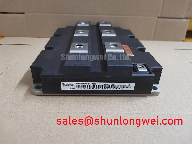
Before installation, verify the equipment nameplate and the original inverter documentation against the 1MBI2400VD-170E rating boundary of 1700 V and 2400 A, then inspect the module terminals, mounting surface, busbar contact areas, and gate-drive connections with the DC link fully discharged.
The Fuji Electric 1MBI2400VD-170E is an IGBT Module rated at 1700 V and 2400 A as an Official Datasheet Specification. For maintenance planning, these values define the electrical identity of the replacement module, but they do not by themselves establish the permissible DC-link voltage, switching frequency, overload profile, cooling capacity, or short-circuit protection setting of the finished inverter.
When evaluating this module for a traction inverter, industrial converter, large motor drive, or energy-conversion cabinet, technicians should compare the original circuit topology, conductor arrangement, driver-board interface, protection behavior, and heatsink assembly. High-speed rail and heavy-freight locomotive traction inverters are possible evaluation contexts, subject to the original equipment documentation and system-level qualification requirements.
| Item | Specification Status | Value |
|---|---|---|
| Part Number | Product Identification | 1MBI2400VD-170E |
| Manufacturer | Product Identification | Fuji Electric |
| Voltage Rating | Official Datasheet Specification | 1700 V |
| Current Rating | Official Datasheet Specification | 2400 A |
| Package Type | Official Datasheet Specification | Module |
1MBI2400VD-170E Thermal-Electrical Optimization: Optimizing Gate-Drive Loop Geometry for Practical Tuning
Gate-loop inspection should start before any dynamic tuning work. Trace the gate and emitter return conductors from the driver board to the installed 1MBI2400VD-170E, looking for shared high-current return paths, loose low-voltage terminals, damaged insulation sleeves, and conductor routes that pass unnecessarily close to the power bus. A gate reference that shares impedance with the main emitter current path can introduce switching noise into the gate signal and may contribute to ringing, irregular switching transitions, or false driver protection activity.
Design Consideration: where the original module documentation and inverter layout provide a dedicated auxiliary emitter reference, keep that gate-drive return separate from the main high-current emitter route. The purpose is to reduce emitter mutual coupling during fast current transitions. The main power path should remain compact and mechanically supported, while the low-energy control path should be routed with consistent spacing from switching nodes and busbar edges. System engineers should validate the resulting gate-emitter waveform at the module terminals during switching tests rather than relying solely on driver-board measurements.
Clearance and creepage around high-voltage terminals require equal attention. Dust deposits, condensed moisture, carbonized residue, and displaced insulating barriers can lower practical surface insulation performance even where the module itself has not changed. During planned shutdowns, remove conductive contamination from the heatsink area, busbar supports, and terminal insulation components. Check that cable lugs and laminated busbars cannot move toward adjacent live metalwork under vibration or thermal expansion.
Transient voltage control is also a system function. MOV networks, snubber circuits, and DC-link capacitors should be checked against the original inverter design, particularly after replacement of power modules or busbar assemblies. Their role is to limit switching-related overshoot, but their selection and placement are determined by the complete commutation loop, available fault energy, and measured voltage margin. The Fuji Electric brake chopper IGBT module information provides related context for evaluating IGBT switching devices used in power-conversion topologies.
Where a repair involves a different inverter branch or a separate power stage, the 6MBI300U-120 can be reviewed as a separate module reference for associated converter or auxiliary-stage evaluation. It should not be treated as an automatic electrical replacement for the 1MBI2400VD-170E; voltage class, current requirement, topology, terminal arrangement, driver compatibility, and thermal conditions must be confirmed by the system engineer.
Benchtop Waveform Tuning: Mitigating Stress Through Static and Dynamic Current Distribution in the 1MBI2400VD-170E
For parallel current paths, begin with static checks before examining switching waveforms. Measure the physical condition of busbars, compare conductor lengths, inspect joint surfaces, and confirm that each module location has comparable heatsink contact. IGBT conduction behavior can exhibit a positive temperature coefficient in relevant operating regions, which can assist steady-state current sharing under controlled conditions. It does not remove the need to verify actual current distribution, because conductor resistance, thermal gradients, gate-drive timing, and mechanical contact resistance can still produce unequal loading.
Dynamic current sharing depends strongly on symmetry in the gate-drive wiring and power loop. Gate leads that differ in route, return reference, connector condition, or termination arrangement can create unequal turn-on and turn-off behavior. Design Consideration: maintain matched physical paths where the original system uses parallel devices, minimize avoidable loop inductance, and verify current and voltage waveforms with appropriate differential probes and current measurement tools. A mismatch may indicate layout or driver-path differences, but it should be investigated against a known-good inverter branch before assigning a cause.
The thermal interface between the module base and heatsink is a frequent maintenance variable. A thin, continuous thermal interface material layer is needed to fill surface irregularities without creating excessive thermal resistance. A 50 to 80 µm thermal interface material thickness is a General Industry Design Consideration where the flatness and material specification support that process; it is not an official mounting requirement for this specific module. The original equipment assembly procedure remains the controlling reference.
Use a diagonal cross-pattern tightening sequence so mounting force is distributed progressively across the module baseplate. The final torque must follow the module documentation and equipment service specification. ⚠️ Maintenance Note: After thermal cycling or major service work, monitor terminal contact temperature rise and confirm that the cooling airflow path remains free of dust and blocked filters.
For an engineering comparison involving another Fuji Electric module family, the 2MBI150UC-120 may be examined as a separate product reference. Its use in any equipment requires a documented review of ratings, topology, mechanical interface, protection coordination, cooling conditions, and gate-drive requirements rather than an assumption of direct interchangeability.
1MBI2400VD-170E Operational Boundaries: Evaluating Desaturation Detection Limits
Desaturation protection should be tested as a coordinated driver-and-power-stage function. In a healthy switching event, the driver monitors the power device state through its own sensing network and fault logic. During an overload, shoot-through event, gate-drive interruption, or short-circuit condition, the sensed collector-emitter behavior can move outside the expected operating range. The exact threshold, blanking arrangement, and protection timing belong to the original driver-board design and must be verified against its documentation.
Design Consideration: short-circuit response is generally assessed within a sub-10 µs protection window when evaluating IGBT safe-operating-area limits, but the applicable duration for the installed module must be taken from the relevant manufacturer documentation and verified at the system level. Do not transfer a timing value from a different module series, inverter generation, or driver platform. Differences in bus inductance, DC-link voltage, fault current rise, temperature, and driver propagation delay can materially change the stress seen by the module.
A two-stage soft turn-off strategy can be used in suitable driver systems to reduce abrupt current interruption after a detected fault. Its aim is to avoid creating excessive inductive overvoltage while still removing gate drive quickly enough to respect the applicable protection boundary. The gate resistor network, soft-turn-off path, fault latch behavior, and clamp coordination should be assessed as one circuit. System engineers should capture collector-emitter voltage and current during controlled protection testing, confirming peak behavior against the DC-link condition and the permitted module limits.
Inspection of the surrounding protection hardware should include desaturation diodes, isolated driver supplies, optical couplers or digital isolators, local decoupling capacitors, and gate connector retention. Common-mode transient immunity is a driver-interface performance requirement, not a property that can be assigned to the IGBT module alone. If nuisance protection trips occur, compare control signals and power-stage waveforms with a known-good path. The behavior may indicate common-mode coupling, grounding changes, degraded driver supply stability, or a gate-loop disturbance.
Industrial environments also require practical moisture control. Condensation around control connectors, gate terminals, and high-voltage insulation barriers may contribute to leakage paths or intermittent measurements. Before energizing serviced equipment, confirm enclosure sealing, airflow condition, heater operation where fitted, and the absence of moisture residue on exposed insulation surfaces.
Preventing Spurious Faults: Thermal Time Constants and Peak Junction Guidelines for 1MBI2400VD-170E
Peak junction evaluation begins with measured operating conditions, not with a single case-temperature reading. Under pulsed overload, the semiconductor junction responds more rapidly than the heatsink and cabinet temperature sensors. A thermal model using the manufacturer-provided junction-to-case transient characteristics can help engineers estimate the relationship between pulse energy, case temperature, and junction excursion. This is an Engineering Calculation only when it uses the applicable published thermal data, measured current waveform, switching losses, conduction losses, pulse duration, and cooling conditions.
The 1MBI2400VD-170E rating of 1700 V and 2400 A should be treated as its official electrical identity, while actual junction stress remains system-determined. Engineers should evaluate the cooling plate condition, thermal interface aging, fan performance, coolant flow where applicable, contact pressure, and load profile. A heatsink that appears acceptable at steady state can still be inadequate for repeated overload pulses if heat accumulation is not considered across the duty cycle.
Thermal troubleshooting is most reliable when several observations are compared. Inspect thermal compound coverage after disassembly, look for uneven contact patterns, verify that mounting hardware has not relaxed, and compare temperature behavior between equivalent inverter positions. A localized temperature increase may be associated with airflow obstruction, thermal interface degradation, unequal current sharing, abnormal switching loss, or a weakened electrical joint. The diagnostic path should use measured evidence rather than a single assumed failure mechanism.
Design Consideration: high-altitude operation, cosmic-ray exposure, single-event burnout risk, insulation reliability, and lifetime prediction require application-specific qualification data. No fixed failure-rate, service-life, or altitude-derating figure should be assigned to this module without authoritative source documentation and system-level analysis. For practical integration topics covering gate drive, thermal management, and power-circuit topology, review the IGBT Design & Integration engineering guide alongside the original equipment documentation.