


Content last revised on June 23, 2026
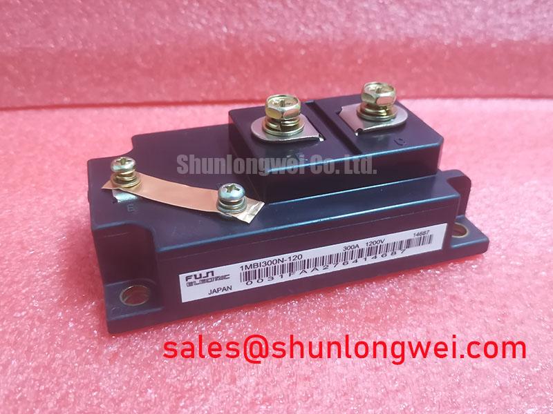
1MBI300N-120 IGBT Module: 1200V, 300A for High-Efficiency Power Conversion
A Datasheet-Driven Analysis for Engineering Professionals
The Fuji Electric 1MBI300N-120 delivers exceptional efficiency in high-power applications by targeting the fundamental sources of energy loss: conduction and switching. This single-pack IGBT module is defined by its core specifications: 1200V | 300A | VCE(sat) 2.3V (typ). Its primary engineering benefits include a significant reduction in thermal design complexity and the capability to operate at higher switching frequencies. For designers evaluating options for demanding motor drives or uninterruptible power supplies, this module addresses the critical need for high efficiency by leveraging advanced trench gate and field-stop silicon technology. Best fit for high-frequency switch-mode power supplies and motor drives where minimizing thermal load is a primary design driver.
Application Scenarios & Value
Achieving System-Level Benefits in Industrial Drives and Power Supplies
The 1MBI300N-120 is engineered to solve critical challenges in modern power electronics, particularly within Variable Frequency Drive (VFD) and Uninterruptible Power Supply (UPS) systems. In a VFD application, a primary engineering challenge is managing heat dissipation within increasingly compact enclosures. The module's exceptionally low collector-emitter saturation voltage (VCE(sat)) of 2.3V at its nominal 300A current directly confronts this issue. This parameter is analogous to the resistance of a mechanical switch; a lower value means less energy is wasted as heat during operation. This reduction in conduction loss lessens the burden on the cooling system, potentially allowing for a smaller, more cost-effective heatsink and improving overall system reliability and power density.
Similarly, in high-power UPS systems, efficiency is paramount to reducing operational costs. The module's optimized switching characteristics and the integrated soft and fast recovery Free Wheeling Diode (FWD) minimize energy losses during the rapid on/off cycles inherent to Pulse Width Modulation (PWM) control. This results in higher conversion efficiency, reduced EMI filtering requirements, and enhanced system robustness. For applications demanding higher current capacity within the same voltage class, the related 1MBI400N-120 offers a 400A rating.
Key Parameter Overview
A Functionally Grouped Specification Table
The following parameters are derived from the official datasheet and represent the core electrical and thermal performance indicators for the 1MBI300N-120. These specifications are essential for accurate system modeling and thermal management design.
| Absolute Maximum Ratings (at Tc=25°C unless otherwise specified) | ||
| Parameter | Symbol | Value |
| Collector-Emitter Voltage | Vces | 1200V |
| Gate-Emitter Voltage | Vges | ±20V |
| Collector Current (DC, Tc=80°C) | Ic | 300A |
| Collector Power Dissipation (Tc=25°C) | Pc | 1470W |
| Operating Junction Temperature | Tj | +150°C |
| IGBT Electrical Characteristics (at Tj=25°C) | ||
| Collector-Emitter Saturation Voltage (Ic=300A, Vge=15V, Tj=125°C) | VCE(sat) | 2.3V (Typ) / 2.8V (Max) |
| Gate-Emitter Threshold Voltage | VGE(th) | 5.0V to 7.0V |
| Input Capacitance | Cies | 24 nF (Typ) |
| FWD Electrical Characteristics (at Tj=25°C) | ||
| Forward Voltage (If=300A, Vge=0V, Tj=125°C) | Vf | 2.1V (Typ) / 2.6V (Max) |
| Reverse Recovery Energy (If=300A, Tj=125°C) | Erec | 15.0 mJ (Typ) |
| Thermal Characteristics | ||
| Thermal Resistance (Junction to Case, IGBT) | Rth(j-c) | 0.085 K/W (Max) |
Download the 1MBI300N-120 datasheet for detailed specifications and performance curves.
Technical Deep Dive
A Closer Look at the Silicon Technology for Minimizing Losses
The performance of the 1MBI300N-120 is rooted in Fuji Electric's advanced silicon design, which employs a combination of trench gate structures and field-stop (FS) technology. The trench gate architecture increases the channel density on the silicon die, effectively creating a wider path for current to flow. This is the mechanism that achieves the low VCE(sat) value, directly reducing conduction losses. Concurrently, the FS layer and thin wafer technology optimize the charge carrier profile within the device. This allows for faster and more controlled turn-off behavior, significantly reducing the "tail current" that is a major contributor to switching losses. This synergistic design approach is fundamental to enabling higher operating frequencies and improving the overall efficiency detailed in resources like this guide to decoding IGBT datasheets.
Frequently Asked Questions (FAQ)
How does the typical VCE(sat) of 2.3V on the 1MBI300N-120 impact system design?
A low VCE(sat) directly reduces power dissipated as heat during conduction (P = VCE(sat) * Ic). This lower thermal load simplifies heatsink selection, potentially reducing its size, weight, and cost. It also creates more thermal margin, which can be used to increase the system's power output or enhance its long-term reliability by operating at a lower junction temperature.
What is the significance of the soft and fast recovery diode integrated into the module?
The soft and fast recovery characteristics of the internal Free Wheeling Diode (FWD) are crucial for reducing electromagnetic interference (EMI). A "soft" recovery minimizes abrupt changes in current, which reduces voltage overshoots and ringing across the IGBT during turn-on. This leads to a cleaner switching waveform, lessening the need for external snubber circuits and simplifying EMI compliance efforts.
The datasheet specifies a 10µs short-circuit withstand time. Why is this critical for reliability in applications like motor drives?
The short-circuit withstand time is a critical safety and reliability parameter. In a motor drive, events like a phase-to-phase short or a motor stall can cause extremely high currents to flow through the IGBT. The 10µs rating ensures the device can survive this stress for a sufficient duration, giving the gate drive and control circuitry time to detect the fault and safely shut down the system, thereby preventing a catastrophic module failure. This is a key aspect of building a robust and fault-tolerant power stage, a topic further explored in IGBT failure analysis.
For detailed application notes or to discuss how the 1MBI300N-120 can meet the specific thermal and efficiency requirements of your project, please contact our technical support team for an engineering-level consultation.