
Content last revised on October 7, 2026
Optocoupler vs Digital Coreless Transformer Isolation in High-Voltage Switching
Before energizing a forklift traction inverter, isolate the 2MBI150U4A-120 from the DC link and verify the module’s marked terminals, gate drive reference, and cold resistance against the equipment service documentation. This initial inspection helps separate a module-side issue from a gate-driver, wiring, or controller fault.
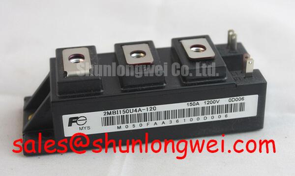
The Fuji Electric 2MBI150U4A-120 is an IGBT module with a rated voltage of 1200 V and a rated current of 150 A. These are the available factory parameters for this product page. The complete switching limits, gate-emitter voltage range, short-circuit withstand capability, thermal resistance, isolation rating, terminal arrangement, and switching test conditions should be confirmed from the original Fuji Electric documentation before a repair or redesign is approved.
In an electric forklift traction inverter, the isolation barrier is part of the gate-drive system rather than a property that can be assumed from the power module alone. Optocouplers and digital coreless transformer isolators use different transfer mechanisms, propagation delays, common-mode behavior, and reset characteristics. The designer should verify the selected driver’s required galvanic isolation rating and common-mode transient immunity from its own manufacturer documentation. Values such as isolation above 5 kV or CMTI above 100 kV/µs are system component requirements to verify, not official specifications of the 2MBI150U4A-120.
When a gate signal appears correct at the controller but the collector-emitter waveform shows an unexpected pulse, probe the signal at the driver output and again at the module gate terminal. Use an appropriately rated isolated differential probe, because a long oscilloscope ground lead can distort the measured gate waveform and may create a hazardous connection. Compare the high-side and low-side paths under the same DC-link and load conditions, then inspect the driver supply, enable state, fault reset timing, and gate-emitter return path.
Clearance and creepage around the isolation barrier must be checked against the applicable equipment insulation strategy, pollution level, working voltage, and safety standard. The module’s presence does not certify the complete forklift inverter for electrical safety or EMC compliance. The system integrator remains responsible for verifying the barrier, enclosure, cable routing, and conducted and radiated emissions at equipment level.
For switching behavior reference, engineers can review Fuji Electric information on Fuji Electric RC-IGBT modules and the manufacturer’s brake chopper IGBT modules. These resources provide application context, but they should not be treated as a substitute for the exact documentation of this model.
Optimizing Heatsink Contact Pressure and Surface Roughness for Minimum R_th(c-s)
Remove the old interface material from both the module base and heatsink, then inspect the contact surface for burrs, raised metal, contamination, or visible distortion. The thermal path depends on actual contact quality, not on the current rating alone. A 150 A rating is an official product parameter, while the permitted operating current in a forklift inverter depends on switching frequency, duty cycle, ambient temperature, cooling conditions, case temperature, and the manufacturer’s derating curves.
A thermal interface material can reduce microscopic air gaps, but excessive compound can increase thermal resistance and migrate during vibration. A controlled film in the approximate range of 50 to 100 µm may be used as a general design consideration when the selected interface material and mounting method support that thickness. It is not an official application requirement for the 2MBI150U4A-120. The material supplier’s spread method, compression behavior, electrical insulation properties, and temperature rating must be checked before production use.
Baseplate curvature should be measured or assessed with the equipment manufacturer’s approved method. Do not force a visibly distorted module flat by tightening one corner first. Start all mounting hardware by hand, bring the fasteners down in a diagonal sequence, and apply the specified torque in stages according to the module and heatsink documentation. ⚠️ Field Alert: never use a high torque value as a substitute for correcting a warped heatsink or contaminated contact surface, because local pressure can damage the module base or ceramic insulation.
The traction environment also makes mechanical retention important. Forklift vibration, repeated acceleration, and cable movement can transfer stress into the module terminals and busbar joints. Support heavy DC-link conductors independently, avoid using the module terminals as cable restraints, and inspect for loosened hardware after controlled vibration or service intervention. Any required M5 torque must come from the relevant mechanical drawing or equipment service instruction; a generic torque value should not be presented as a Fuji Electric specification for this model.
Parasitic busbar inductance is controlled by loop geometry, conductor spacing, return-path proximity, and the physical location of the DC-link capacitor. A target such as 25 nH may be a system design objective in a particular inverter, but it is not an official parameter supplied here for the 2MBI150U4A-120. Designers should minimize the commutation loop and verify the resulting overshoot with a properly connected differential probe during switching tests.
Film capacitors used for high-frequency suppression should be placed according to the actual commutation loop rather than at a convenient point elsewhere in the cabinet. Their voltage rating, pulse current capability, self-resonant behavior, and mechanical retention require separate verification. If a heatsink temperature rises unexpectedly, record case temperature, coolant or airflow conditions, switching pattern, gate waveform, and load current before replacing the module. Thermal symptoms can originate in the interface, cooling system, gate drive, current measurement, or switching loss.
Turn-Off di/dt Induced V_peak Clamping and Snubber Capacitor Sizing
During turn-off, the measured collector-emitter peak is influenced by DC-link voltage, commutation-loop inductance, current fall rate, gate resistance, diode recovery behavior, and probe placement. In engineering analysis, the relationship is commonly expressed by treating the inductive contribution as proportional to stray inductance and current slew rate, so the observed peak rises above the DC-link voltage when the switching loop is not sufficiently controlled. This relationship is an engineering calculation framework, not a substitute for the module’s official switching curves.
For the 2MBI150U4A-120, the voltage rating is 1200 V. The system engineer should verify the actual DC-link operating range, transient peak, repetitive stress, and temperature-dependent margin against the original datasheet and the forklift inverter’s protection strategy. Do not infer a safe switching voltage from the model name or from the 150 A current rating.
Snubber capacitor selection requires measurement of the actual overshoot and ringing frequency. Increasing capacitance may reduce the first voltage peak, but it can also increase turn-on or turn-off current, capacitor RMS current, switching loss, and mechanical stress in the busbar. Select the capacitor only after checking its pulse capability, voltage rating, ESR, ESL, temperature performance, and physical placement. The final value is system-determined and should be validated at minimum and maximum battery voltage, cold and hot conditions, and representative traction loads.
Keep the snubber connection short and symmetrical across the switching path. A planar busbar arrangement with a close forward and return path generally reduces loop area, while a remote capacitor connected through long leads can add inductance that defeats the intended suppression. If the oscilloscope trace shows ringing, first repeat the measurement with a shorter probe connection and confirm the reference point. Then compare the same switching event at different currents and gate-drive settings.
When a repaired inverter repeatedly reports overvoltage or gate-driver faults, inspect the DC-link capacitor connection, laminated busbar joints, module terminal clamping, diode commutation path, and current sensor orientation. An apparently identical fault can result from loose hardware, an unsuitable snubber, incorrect gate timing, driver supply instability, or an incorrectly connected replacement module. Record waveforms before changing several variables at once.
For broader procedures covering electrical checks, thermal inspection, switching waveform capture, and failure analysis, engineers may consult the Field Engineer’s Handbook. The handbook can support a test plan, but product-specific acceptance limits still require the original Fuji Electric documentation and the equipment manufacturer’s service criteria.
Dynamic Gate Impedance Control for Robust Phase-Leg Dead-Time Operation
Gate-loop layout should be treated as a high-current switching circuit, even though the gate current is much smaller than the traction current. Keep the driver output path and gate-emitter return path compact, route them as a close pair where practical, and avoid sharing the gate return with power-current paths. The exact terminal arrangement and any auxiliary emitter connection must be verified from the module drawing before a PCB or busbar is released.
High collector-voltage slew rates can couple through the Miller capacitance and disturb the opposite device in a phase leg. A dedicated active Miller clamp may reduce the risk of an unintended gate rise when the driver supports that function. Its suitability depends on driver architecture, clamp current, propagation delay, gate resistance, parasitic inductance, and the module’s permitted gate-emitter conditions. It should be validated with a differential gate probe during the complete switching sequence.
A negative gate bias in the range of −5 V to −15 V is a possible system-level design choice for some isolated IGBT drivers, but it must not be applied to this module without confirming the exact Fuji Electric gate-emitter voltage limits and the driver’s power-up and fault behavior. The negative rail also requires controlled sequencing so that the gate is not left at an undefined potential during startup, shutdown, brownout, or isolation reset.
Dead time should be established from measured turn-off and turn-on behavior rather than copied from an unrelated module. Excessive dead time increases diode conduction and can raise losses, while insufficient dead time can permit cross-conduction under temperature, current, and driver-delay variation. Verify both complementary gate signals at the module terminals, then check collector-emitter voltage and phase-leg current during cold start, hot operation, low battery voltage, and maximum commanded torque.
A practical starting point for bench tuning is to add gate damping only after confirming the driver supply, gate return, and measurement setup. The appropriate resistance is system-dependent; changing it affects switching loss, voltage overshoot, electromagnetic behavior, and short-circuit response. Designers should also verify the gate-driver desaturation or overcurrent response, fault latch behavior, reset timing, and isolation power supply under the same conditions.
For equipment integration, inspect FPC or control-board connectors, locking features, cable strain relief, and vibration exposure separately from the power module. A stable gate waveform at the driver can still become unreliable if a connector contact intermittently opens or a harness moves relative to the inverter chassis. Before final release, document the module’s 1200 V voltage rating, 150 A current rating, verified terminal mapping, measured switching waveforms, cooling conditions, and the system-specific protection limits.