Content last revised on October 3, 2026
Preventing Spurious Faults: Desaturation Detection for 2MBI200-060
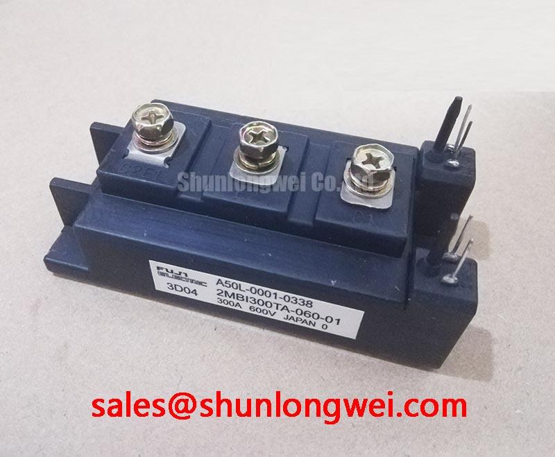
2MBI200-060 | Fuji Electric | IGBT module | Fuji Power Module package | Rated voltage: 600 V (Official Specification) | Rated current: 200 A (Official Specification)
Probe the gate-to-emitter waveform and the driver fault output during a controlled switching test if the drive trips without a clear load fault. On the 2MBI200-060, a desaturation indication calls for checking the complete protection path: sensing connection, blanking behavior, gate drive and the power circuit. A noisy sense path can resemble a collector-voltage fault, while a genuine short circuit may present a sharply rising collector voltage during commanded conduction. Neither observation establishes the cause on its own.
Desaturation protection is a system-level Design Consideration, not a stated operating parameter of this module. The driver must distinguish switching transients from sustained abnormal conduction and remove gate drive before the module exceeds its documented safe operating limits. Short circuits that occur during turn-on and those that develop while the device is already conducting can produce different waveforms. Capture both the fault signal and collector-to-emitter voltage during controlled tests, then assess the protection timing against the applicable Fuji documentation and the installed driver circuit rather than assigning a universal trip time.
Route the sensing and gate-return paths away from high-current switching conductors where the assembly permits, and inspect connector seating before changing protection settings. A staged, controlled turn-off may help contain inductive voltage overshoot after a detected fault, but its waveform and peak voltage require validation on the actual busbar and DC link. Fuji Electric’s High-Speed Discrete IGBTs illustrate a separate product category; their switching or protection figures must not be transferred to this module.
2MBI200-060 Thermal Interface and Baseplate Contact
Inspect the module-to-heatsink contact pattern when case temperature rises under a previously manageable load. Uneven thermal compound, debris or a distorted mounting surface can interrupt heat transfer even when the heatsink fan is running. Clean the mating surfaces, check flatness against the assembly requirements and apply thermal interface material according to the approved mounting procedure. Use a controlled fastening sequence so the baseplate seats evenly; obtain the specified fastener torque from the applicable mechanical documentation rather than treating a general workshop value as a Fuji rating.
Thermal compound thickness is a Design Consideration governed by the mating surfaces and the material selected. Aim for continuous contact without trapped voids or excessive buildup, and examine the removed module’s contact imprint for evidence of poor seating. If temperature readings change after remounting, compare them at the same load, coolant or airflow condition and sensor location. Those checks are more useful than attributing every hot spot to the semiconductor.
Electrical layout affects the same repair decision. Minimize the power commutation loop and place the system’s snubber film capacitor where it can effectively limit turn-off overshoot; confirm the result by measuring collector-to-emitter peaks during representative switching. The acceptable layout and peak margin are determined by the installed circuit, not by the module’s 600 V Official Specification alone. For an industrial inverter welder or medium-frequency induction-heating supply, assess both the thermal mounting and the original busbar geometry before considering a mechanical change.
Benchtop Gate Waveforms: Miller Coupling and Turn-Off Control
Measure the off-state gate-to-emitter voltage while the opposite switch commutates if the drive reports intermittent overcurrent or both devices appear to conduct. Collector-voltage transitions can couple into the gate circuit through the Miller capacitance; wiring inductance and a high-impedance turn-off path may amplify the observed disturbance. Compare the trace with the driver command and collector waveform before changing components. Probe at the module connections where safe test access permits, because a waveform measured only at the driver board may hide voltage developed along the gate loop.
A low-impedance active Miller clamp and negative gate bias are possible driver-level Design Considerations, not built-in features or prescribed settings for 2MBI200-060. Select either approach only after checking driver capability, the module’s documented gate limits and the switching behavior of the assembled equipment. Keep the gate and return paths compact to reduce parasitic ringing, then verify that any damping change controls oscillation without creating unacceptable turn-on loss or turn-off overvoltage. Fuji Electric’s RC-IGBT Modules describe a different module family and do not establish gate-drive settings for this part.
For a replacement assessment, 2MBI200J-120 is a separate Fuji Electric model to evaluate, not an assumed drop-in substitute. Compare its complete electrical ratings, terminal arrangement, mounting geometry and driver requirements with the existing assembly before approving a change.
2MBI200-060 Circuit Protection and Pulsed Thermal Stress
Record case temperature and load-current waveforms through a representative duty cycle when trips follow bursts rather than steady operation. The 200 A Official Specification identifies the rated current, but it does not by itself define permissible pulse duration, cooling performance or junction-temperature margin in a particular installation. Check the applicable thermal and safe-operating-area data before using a transient thermal model to assess peak junction temperature. Such a model needs the actual loss waveform and documented thermal impedance; a steady-state heatsink reading cannot substitute for them.
Separate electrical stress from cooling faults during diagnosis. Compare fault timing with bus voltage, current and turn-off overshoot, then inspect the heatsink airflow path, mounting contact and terminal tightness. Seasonal humidity and condensation also warrant enclosure checks because moisture at external connections can complicate insulation and fault diagnosis. These are maintenance Design Considerations, not claims about this module’s certified environmental limits.
Maintenance note: Isolate and discharge the equipment before inspecting terminals, thermal compound or the heatsink airflow path. If the fault recurs after mechanical and cooling checks, retain synchronized waveforms rather than repeatedly raising protection thresholds. The Power Electronics Masterclass provides broader context for reviewing IGBT selection and system reliability; the repair decision still depends on measurements from the installed equipment.