Content last revised on September 10, 2026
Assembly Integrity and Layout Architecture for Thermal Feedback
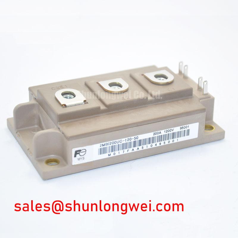
Before installation, verify the module marking, inspect the insulating base and terminals, and confirm the equipment DC bus and switching transients remain within the 1200 V collector-emitter rating. The Fuji Electric 2MBI200HH-120-50 is a high-power IGBT module specified with a rated collector current of 200 A, with a maximum power dissipation of 1500 W. It is suitable for engineering evaluation in industrial inverter, traction, regenerative braking, and motor-drive assemblies where the original electrical and mechanical interfaces are confirmed.
| Parameter | Official Specification |
|---|---|
| Manufacturer | Fuji Electric |
| Collector-emitter voltage, VCES | 1200 V |
| Rated collector current, IC | 200 A |
| Maximum power dissipation, PD | 1500 W |
| Isolation voltage, VISO | 2500 V AC for 1 minute |
| Collector-emitter saturation voltage, VCE(sat) | 3.50 V typical |
| Gate-emitter threshold voltage, VGE(th) | 4.5 V to 8.5 V |
| Turn-off time, toff | 0.50 µs maximum |
| Junction-to-case thermal resistance, Rth(j-c) | 0.085 °C/W for the IGBT |
During replacement work, measure the gate-emitter and power-terminal condition against a known-good module before applying the DC bus. A cold resistance or diode-check result is only a screening observation, not proof of switching health. The gate-drive board, emitter reference, and power commutation path should be checked together because an apparently healthy module can behave incorrectly when the driver return path is asymmetric.
Design Consideration: VCE(sat) can exhibit a positive temperature relationship in steady-state operating regions, which may support static current-sharing behavior when paralleled devices use matched thermal conditions. Dynamic sharing remains dependent on gate-loop inductance, driver timing, stray inductance, and busbar geometry. Keep corresponding gate and emitter conductors physically symmetrical, minimize the high-current commutation loop, and verify turn-on and turn-off waveforms with an oscilloscope under the actual gate-drive arrangement.
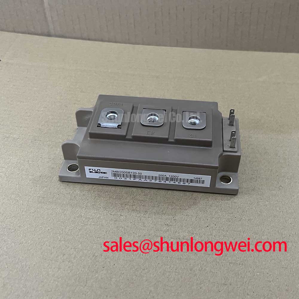
For electric material handling and forklift low-voltage traction systems, confirm that the module topology, freewheel path, braking chopper arrangement, and controller protection sequence match the original assembly. Engineers comparing a related Fuji Electric module may review 2MBI200UB-120 as a separate device reference, but electrical, mechanical, and gate-drive compatibility must be established by the system designer rather than assumed from the voltage class.
Benchtop Waveform Tuning Under Pulsed Thermal Stress
A short overload pulse does not immediately produce the same junction temperature as a steady load. The case, baseplate, heatsink, and thermal interface material absorb heat at different rates, so a transient thermal model should be used when evaluating repetitive traction current, regenerative braking, or motor acceleration. The official Rth(j-c) of 0.085 °C/W provides the junction-to-case portion of the thermal path; the remaining case-to-heatsink and heatsink-to-air behavior is determined by the assembly.
When applying a thermal RC model, use measured case temperature, pulse duration, duty cycle, and the actual cooling boundary rather than treating the maximum 1500 W dissipation value as an unrestricted operating target. Check VCE(sat), collector current, switching overshoot, and gate waveform together. A change in saturation voltage or switching shape may require inspection of the driver supply, gate resistor path, busbar connections, and thermal contact before the module is condemned.
For a controlled bench comparison, apply the TIM as a uniform film appropriate to the selected material and heatsink finish. A 50 to 80 µm target may be used only as a typical starting point when the TIM supplier and mechanical drawing support it; the system engineer must verify coverage, compression, and resulting case temperature. Cross-pattern tightening is a general assembly practice for distributing pressure, while the permitted torque must follow the module manufacturer’s mechanical documentation and fastener specification.
Heatsink Contact Pressure, TIM Control, and Field Maintenance
Remove oxide, dust, excess compound, and burrs from the contact surfaces before mounting. Inspect the baseplate for curvature or local high spots, then check that the heatsink is adequately supported without forcing the module into mechanical distortion. Excess TIM can increase thermal resistance, while insufficient coverage can leave air pockets; the correct condition is confirmed by the interface material instructions and temperature measurements taken during a controlled load test.
Terminal hardware should be tightened with a calibrated tool and rechecked after thermal cycling where the equipment maintenance procedure requires it. In high-humidity or low-temperature areas, inspect for condensation, contamination tracks, and corrosion around the insulated power terminals. The 2500 V AC isolation specification for 1 minute is a stated electrical test rating, not a substitute for system-level creepage, clearance, pollution-degree, enclosure, and cleaning requirements.
Maintenance Note: Monitor contact temperature and clean the heatsink airflow path during scheduled service, especially when thermal readings rise without a corresponding increase in commanded load.
In the rectifier and auxiliary power section, the related 2MBI300U4H-120-50 may be evaluated as a separate topology reference. Phase-controlled rectifiers can introduce line-current distortion, so harmonic mitigation, firing-angle control, input filtering, and grid constraints should be assessed at system level rather than attributed to the IGBT module alone.
DC-Bus Headroom and High-Altitude Reliability Assessment
During switching tests, record the collector-emitter peak voltage at the module terminals, not only at the DC-link capacitor. Parasitic inductance and regenerative braking energy can create turn-off overshoot, so the layout should minimize the commutation loop and the measured peak must be checked against the 1200 V VCES rating under the worst intended operating condition. Brake-resistor energy absorption, chopper duty, motor regeneration, and bus overvoltage protection all remain system-determined functions.
At elevations above approximately 2000 m, reduced air density can affect external insulation coordination and cooling. Terrestrial neutron exposure and single-event burnout risk also require application-specific reliability assessment. No FIT rate, SEB voltage limit, altitude derating curve, or lifetime figure is established by the parameters provided here; these values should not be inferred from the module’s voltage rating. Designers should obtain applicable Fuji Electric reliability guidance and validate the assembled inverter under its real bus voltage, switching conditions, enclosure pressure, and cooling environment. General power semiconductor technology information is available from Fuji Electric Global Power Semiconductor Technologies.
For thermal architecture decisions involving insulated mounting structures or enhanced cooling arrangements, consult The Advanced Thermal Management Revolution as an engineering reference, then confirm the final thermal impedance through measurement on the completed assembly.