
Content last revised on September 18, 2026
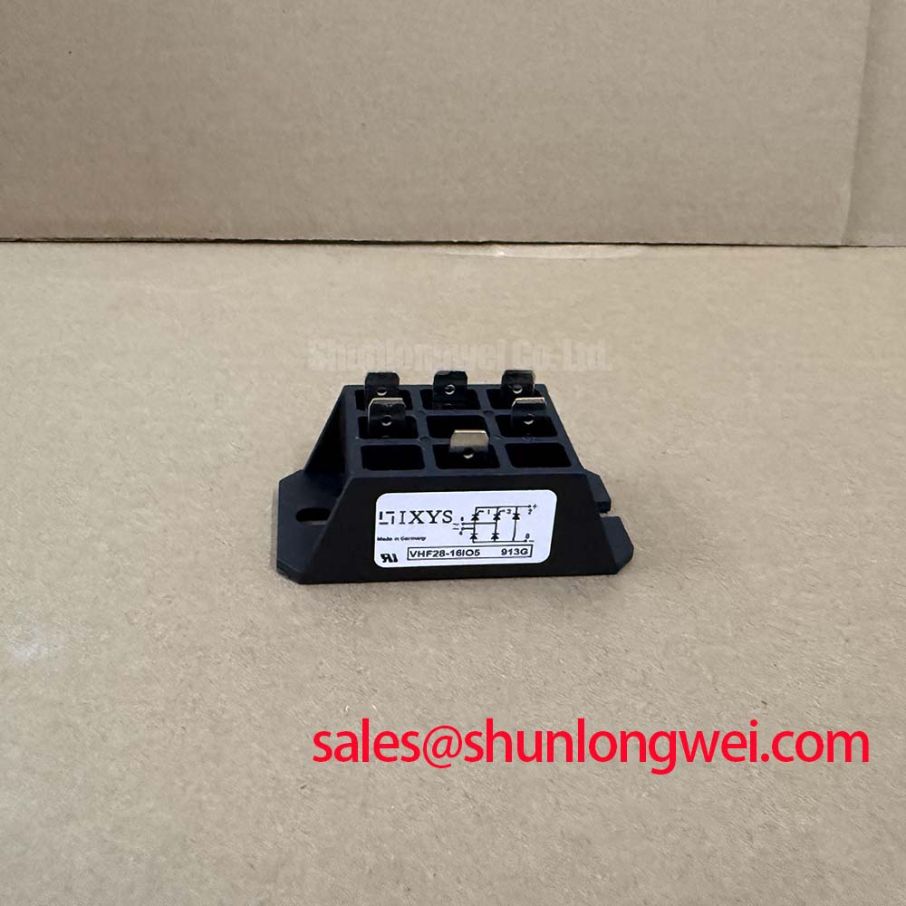
With the rectifier isolated from the supply and DC bus discharged, first inspect the 36MT120A terminals, mounting face, and cable lugs for heat discoloration, loose hardware, cracked insulation, or evidence of uneven clamping. This Vishay bridge rectifier module should then be checked with a meter using diode test in each expected forward path while comparing the readings with the original circuit drawing and a known serviceable assembly where available. A single abnormal reading does not establish one specific failure mode; it can also reflect parallel suppression parts, transformer windings, or external wiring that remains connected.
The 36MT120A Vishay bridge rectifier module is specified with a 1200 V repetitive peak reverse voltage, 35 A average forward current at case temperature of 120°C, and 500 A non repetitive forward surge current for a 10 ms sine wave. Its specified junction temperature range is minus 55°C to 150°C, with 2500 V RMS isolation voltage and a D 63 MTP package. The typical forward voltage is 1.19 V per diode.
| Official Specification | 36MT120A Value |
|---|---|
| Repetitive peak reverse voltage | 1200 V |
| Average forward current | 35 A at TC = 120°C |
| Non repetitive forward surge current | 500 A for 10 ms sine wave |
| Forward voltage per diode | 1.19 V typical |
| Operating junction temperature | minus 55°C to 150°C |
| Isolation voltage | 2500 V RMS |
| Package | D 63 MTP |
Benchtop Waveform Tuning: Mitigating Stress via Sinusoidal 10 ms Half Cycle Surge Current on 36MT120A
The 500 A surge rating is an Official Specification for a non repetitive 10 ms sine wave event. It is not a continuous current rating and should not be used as a recurring operating target during commissioning. In a high current rectifier cabinet, this rating is relevant when examining transformer energization, discharged DC link charging, fault clearing behavior, or a temporary overload that has already occurred.
After any suspected surge event, isolate the bridge and check every AC input to DC output path according to the equipment schematic. Look beyond meter readings: inspect the fuse body, busbar contact surfaces, lug pressure marks, and heat sink interface. A bridge can show normal basic diode behavior while the surrounding connection stack has developed resistance that raises local temperature under load. If waveform capture is available, verify the current shape at startup and before reverse voltage is reapplied to the rectifier.
Fuse coordination is a Design Consideration. The system engineer should compare the fuse manufacturer’s time current and clearing information with the rectifier’s surge capability, expected transformer inrush, and available fault current. A fuse selected only by nominal load current can behave differently during a severe transient than one selected after reviewing its clearing characteristic. No fuse I²t value is stated here as an official parameter for the 36MT120A, so the original equipment protection documentation remains the controlling reference.
The specified 1200 V repetitive reverse voltage must be checked against actual line conditions, transformer secondary behavior, and measured switching transients in the installed cabinet. The module’s 150°C maximum operating junction temperature is also an electrical boundary, not proof that every heat sink arrangement can sustain the rated current. When integrating the module, technicians should verify case temperature, cooling airflow, heat sink cleanliness, and terminal loading under the actual duty cycle.
⚠️ Field Alert: Tighten mounting and terminal hardware only to the torque specified for the installed hardware and equipment drawing, and apply thermal compound as a uniform thin film before final clamping.
For repair documentation, record the original module orientation, AC and DC terminal positions, heat sink condition, and protective device references before lifting the bridge. This avoids reversing the bridge connections during a time sensitive restoration. Where the original design requires a related high current rectifier device, VS ST730C18L0 can be reviewed as a separate component option, subject to full verification of topology, footprint, voltage rating, thermal interface, and electrical requirements by the system engineer.
Assembly Integrity and Layout Architecture: Industrial Surge Immunity for 36MT120A
Heavy AC input wiring should be evaluated as part of the rectifier assembly, not as an afterthought. The 36MT120A bridge receives stress from line disturbances through transformer coupling, input cabling, contactor switching, and the energy stored in the DC side. The 2500 V RMS isolation specification is an Official Specification for the module, but it does not replace system level insulation coordination, enclosure design, wiring clearance assessment, or surge validation.
For industrial surge immunity work, the applicable system standard is commonly referenced as IEC 61000 4 5. A Design Consideration is to position protective stages so that conducted surge energy is managed before it reaches sensitive branches and so that the physical return path does not create a large loop around the bridge and busbars. Metal oxide varistors and RC networks must be selected using the actual supply arrangement, expected surge environment, source impedance, protection coordination, and measured residual voltage. Their values must be established by the equipment design and test results rather than inferred from the 36MT120A rating alone.
A suppression device can control voltage yet still introduce leakage, heating, or an unfavorable failure response if it is not coordinated with the upstream protective device. Inspect MOV condition indicators where fitted, verify snubber capacitor condition, and compare terminal routing against the original layout. Short, direct high current paths are a Design Consideration because they help limit parasitic inductance during rapid current change. Peak voltage margins should be confirmed by switching tests against the DC bus and line conditions actually present.
The basic purpose of a transient voltage suppression stage is to clamp a voltage excursion by entering a conductive state. For a general explanation of that mechanism, see Transient Voltage Suppression Diodes for Surge Protection. This reference explains the principle, but it is not a substitute for module specific qualification or system surge testing.
For a green hydrogen electrolyzer DC power rectifier, the bridge should be assessed within the complete transformer, fuse, busbar, and DC smoothing network. The module can be evaluated for this type of industrial rectification service because of its stated voltage, current, temperature, and isolation parameters, but suitability depends on the actual electrical duty and cooling arrangement. Inspecting current sharing paths and connection symmetry is especially useful where parallel power paths exist elsewhere in the equipment.
Assembly Integrity and Layout Architecture: Power Factor Degradation and Harmonic Mitigation for 36MT120A
The 36MT120A is a diode bridge rectifier module. It has no gate terminal and does not provide firing angle control. Discussions of firing angle, gate trigger current, gate trigger voltage, pulse train triggering, and thyristor commutation do not apply to this module. If the equipment uses controlled rectification, identify the actual controlled semiconductor stage separately before assigning a repair action.
A diode bridge draws current according to the transformer secondary voltage, DC side load, smoothing components, source impedance, and any upstream control scheme. This can affect input current waveform, displacement behavior, and harmonic content at the system level. Power factor or harmonic performance cannot be assigned to the 36MT120A alone. It should be measured at the equipment input under representative load conditions with the original transformer, filtering network, and DC load connected.
During service, first confirm that all bridge terminals are correctly landed and that no AC phase or DC polarity has been exchanged. Then inspect for unequal heating among associated terminals, excessive ripple on the DC output, transformer noise changes, or abnormal upstream protective device operation. These observations may indicate an issue in the bridge, load, transformer, smoothing network, or connections. Oscilloscope and power analyzer measurements against a known good signal path provide more reliable direction than assigning one symptom to one component.
Designers considering input harmonic improvement should evaluate the entire AC to DC conversion path. Depending on the equipment architecture, the relevant work can include transformer impedance, line reactor behavior, passive filtering, active front end equipment, DC link loading, and control behavior outside this bridge module. A related device such as PK55FG120 may be reviewed when documenting complementary rectifier stages, provided its own official ratings and the installed circuit requirements are checked independently.
When assessing rectifier duty in high power conversion equipment, it is useful to distinguish measured component stress from broader architecture decisions. The discussion in The Race for Efficiency provides context for evaluating modular high power conversion layouts. Any transfer of those concepts to an electrolyzer rectifier requires system specific verification.
Transient Dynamics and Electrical Design: Saturable Reactor and Snubber Evaluation for 36MT120A
RC snubbers and series reactors are external circuit elements, not built in functions stated for the 36MT120A. They should be considered when measured turn on or turn off transients, transformer leakage effects, cable inductance, or contactor behavior create voltage and current stress that approaches system limits. The purpose is to control the transient response of the complete assembly, while preserving acceptable thermal performance and normal operating efficiency.
A saturable reactor can be evaluated where the system designer needs to shape the initial rate of current rise under defined fault or switching conditions. Its core selection, saturation behavior, winding resistance, insulation class, and thermal capability must be determined from the installed topology and measured waveform. The bridge rating alone cannot establish a reactor value or prove protection against every localized heating condition.
For RC snubber evaluation, capture voltage across the relevant AC winding, bridge connection, or DC bus during the operating event of concern. Then assess ringing frequency, peak amplitude, recurrence, and the influence of physical wiring layout. The capacitor, resistor, voltage rating, energy capability, and mounting method should be selected from those measured conditions and verified during repeat testing. Avoid placing snubber leads so that they create a long inductive path that weakens the intended damping effect.
The bridge’s 1.19 V typical forward voltage per diode is useful for loss estimation only when considered with the actual current waveform and temperature. It should not be treated as a fixed field diagnostic threshold. If thermal rise is unexpected, examine cooling contact, mounting flatness, airflow, busbar resistance, transformer condition, and load behavior before concluding that the module itself is responsible.
Before returning the rectifier to service, recheck DC polarity, AC terminal assignment, protective earth continuity of the equipment, insulated cover placement, and the clearance of all tools from the enclosure. Apply power under the equipment’s approved commissioning procedure while monitoring input current, DC output behavior, and heat development. The final protection and snubber arrangement remains system determined and should be validated against the actual transient waveforms and operating limits.