Content last revised on October 21, 2026
36MT140A Inspection and Identification
- Confirm the cold resistance and diode direction at each accessible power terminal with the module isolated from the circuit.
- Match the nameplate rating with the replacement record: 35.0 A, Power Block / Bridge Case, and the listed standard industrial operating-voltage classification.
- Inspect the mounting surface, clamping hardware, heatsink contact, and terminal interfaces before applying load.
- Check protective earth, driver cabinet isolation, fuse coordination, and DC bus discharge status before electrical testing.
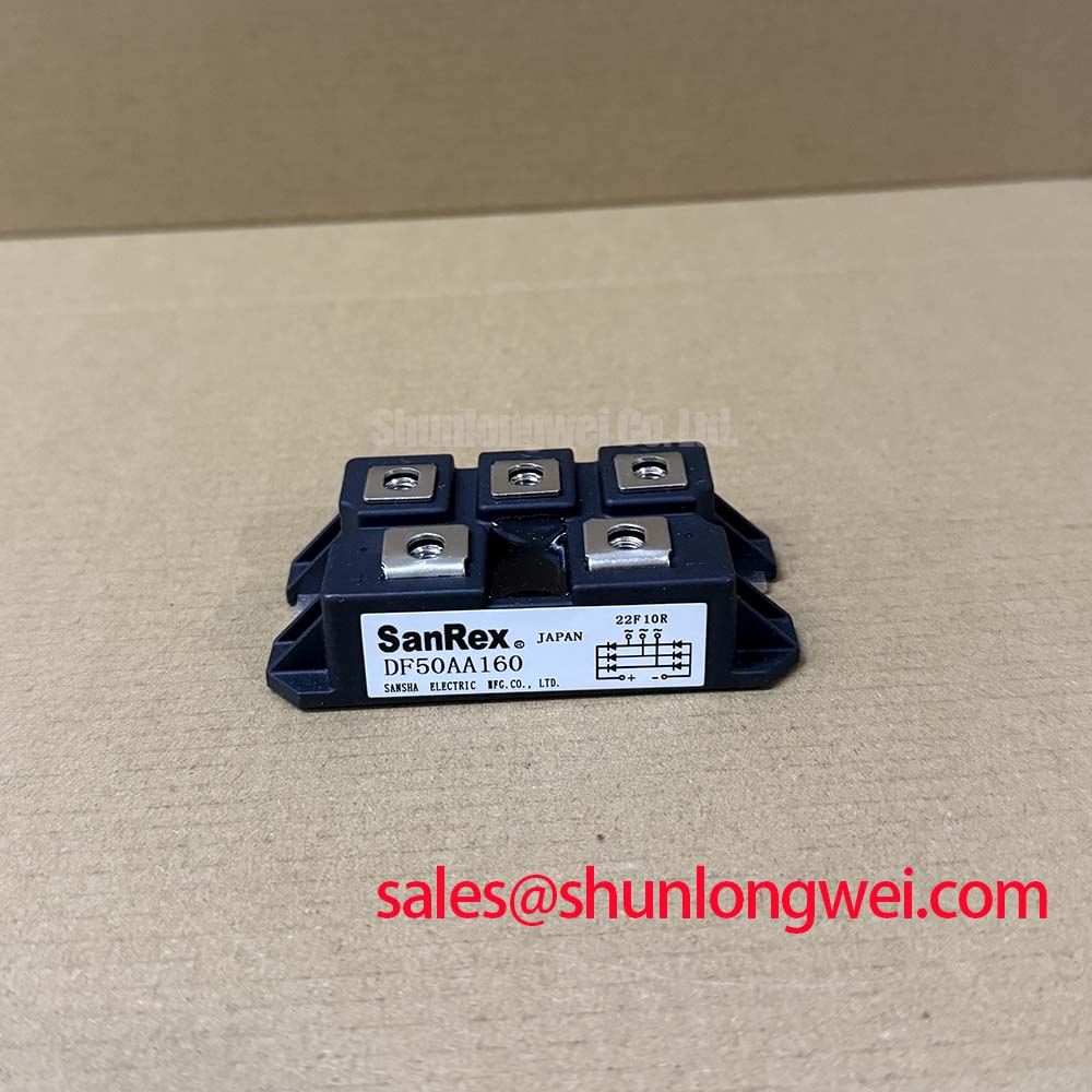
Vishay 36MT140A is identified here as a 35.0 A bridge rectifier module in a Power Block / Bridge Case. Its supplied operating-voltage classification is listed as Standard Industrial Rating; the applicable system voltage must be matched to the original equipment documentation and the current rectifier assembly. This format is commonly evaluated in industrial AC to DC power stages where terminal access, heatsink coupling, and controlled fuse coordination affect service decisions.
| Manufacturer | Vishay |
| Part number | 36MT140A |
| Product category | Bridge Rectifier Module |
| Rated current | 35.0 A |
| Operating-voltage classification | Standard Industrial Rating |
| Package | Power Block / Bridge Case |
For incoming inspection, use the diode test function only after isolating the module and confirming the terminal arrangement from the equipment drawing. Forward readings should be compared across corresponding rectifier paths rather than judged from a single meter value. A significant asymmetry between equivalent paths may justify a second measurement with reversed leads, followed by isolation of parallel wiring, snubber components, and fuse links that can influence the reading.
💡 Bench Tip: Use an ESD-controlled bench and record a cold-state reference before installation so later measurements can be compared with the same terminal polarity and instrument range.
36MT140A Thermal Electrical Optimization for RC Snubber and Fuse Coordination
RC snubber selection around a bridge rectifier is a system-level task: the resistor and capacitor must be selected from the switching environment, commutation behavior, wiring inductance, and measured transient waveform. The 36MT140A should not be assigned a universal snubber value without reviewing the rectifier topology and the original protection network. Designers should place the snubber loop close to the relevant power terminals when the measured circuit requires transient suppression, then verify resistor heating, capacitor voltage stress, and waveform behavior during controlled commissioning.
Long motor or converter cables can create reflected-wave peaks that increase stress on the DC link and rectifier assembly. A practical verification uses a properly rated differential probe at the module terminals and compares the measured peak with the equipment insulation and semiconductor voltage limits. Filter placement, cable routing, and damping remain system decisions. The same principle applies to a high-current green hydrogen electrolyzer DC power rectifier, where transformer leakage, busbar geometry, and rectifier commutation can interact with the protection network.
Fuse coordination should use the applicable manufacturer time-current and I²t data for the selected fuse, not the bridge current rating alone. Check prospective fault current, repetitive overload duty, fuse clearing energy, and the thermal path into the heatsink. A series saturable reactor may be considered where the rectifier system experiences severe current rise or commutation disturbance, but its selection requires measured current sharing and magnetic operating data.
For thermal assembly, clean the contact surfaces, keep the module seated evenly, and use a calibrated fastening method appropriate to the hardware and heatsink. The required mounting torque must come from the relevant assembly instruction rather than from a generic value. The technical discussion in The Advanced Thermal Management Revolution provides broader context on heatsink and double-sided cooling architectures.
Assembly Integrity and Layout Architecture for Rectifier Current Dynamics
The 36MT140A is a bridge rectifier module, so gate-trigger current, gate pulse rise time, and gate holding current are not operating functions of this passive rectifier itself. If a service drawing includes gate-drive measurements, those signals belong to an upstream controlled rectifier, thyristor stage, or another switching device. This distinction prevents a gate-firing fault from being incorrectly assigned to the bridge module.
Assembly integrity instead depends on correct AC terminal routing, correct DC output polarity, low-resistance bus connections, and even mechanical pressure across the mounting base. Verify each terminal against the equipment schematic before energizing. Where several rectifier paths operate in parallel, measure current distribution with suitable probes and inspect busbar symmetry. Heavy-copper PCB practices can be relevant to auxiliary high-current paths; the Heavy Copper PCB reference describes the general role of increased copper thickness in high-current routing.
⚠ Safety Interlock Note: Disconnect power and verify DC-link discharge before removing terminals or changing the rectifier assembly.
Use the original fuse coordination table and wiring geometry when comparing a replacement. Do not assume that a visually similar bridge has the same terminal order, thermal interface, or current-sharing behavior. For thermal validation, airflow, heatsink orientation, enclosure temperature, and contact quality should be measured under the intended duty cycle; CFD can support enclosure airflow analysis, as outlined in this Computational Fluid Dynamics reference.
Preventing Spurious Faults in Multi Bridge Architectures
Six-pulse and twelve-pulse rectifier arrangements require more than multiplying the single-module current rating. The system engineer should assess transformer phase displacement, commutation overlap, busbar impedance, fuse selectivity, and current sharing between parallel bridge sections. In a twelve-pulse arrangement, the phase-shifting transformer and its leakage characteristics influence the interaction between rectifier groups. Where an interphase transformer is used to couple parallel rectifier groups, its leakage and saturation behavior also influence the actual current balance.
The 36MT140A can be evaluated as one rectifier element within such an architecture when its 35.0 A rating and Power Block / Bridge Case interface match the assembly requirements. Current sharing should be verified at the module terminals under the intended load profile rather than inferred from nominal ratings. Uneven temperature rise may lead engineers to inspect busbar symmetry, contact pressure, fuse condition, transformer phase balance, and cooling distribution as a combined diagnostic set.
For a lower-current comparison within the same product family, engineers may review 36MT80A against the original circuit rating and mechanical arrangement. In a broader rectifier chain, 36MT100A may be considered as a neutral reference for a related rectifier stage, subject to electrical, thermal, and terminal compatibility checks. These comparisons do not replace the original equipment bill of materials or protection study.