




Content last revised on September 21, 2026
Assembly Integrity and Layout Architecture for DF50AA160
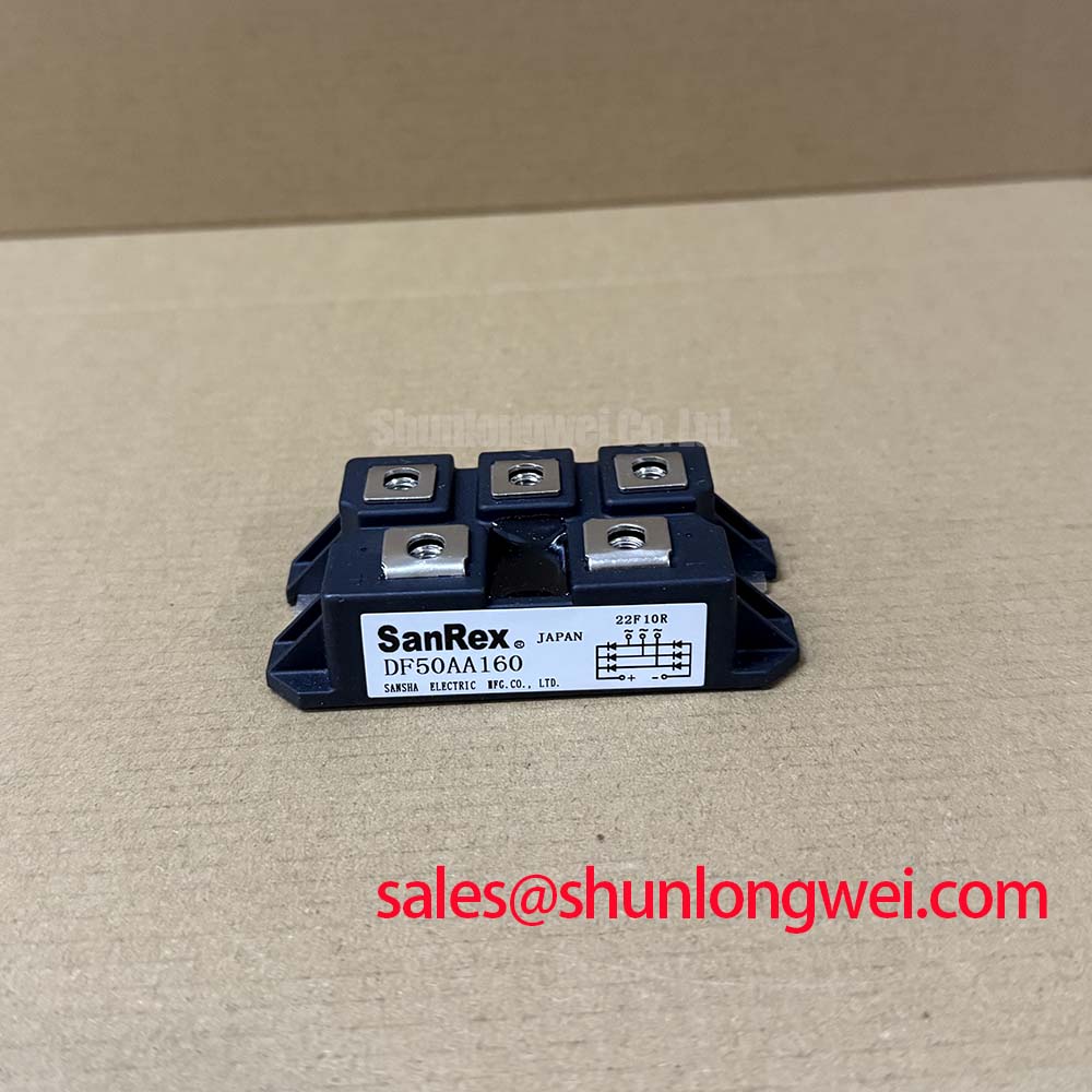
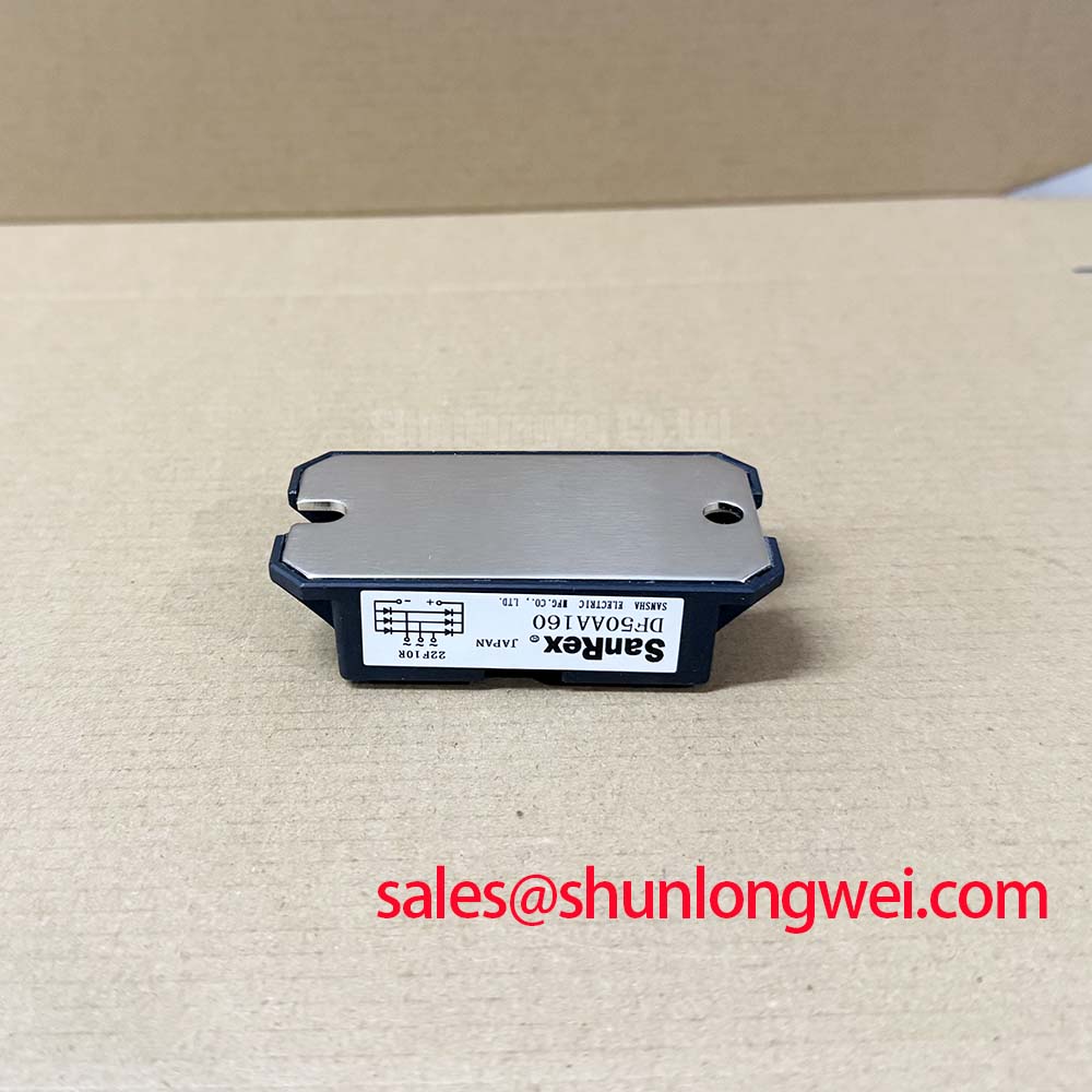
Before connecting a replacement, isolate the assembly, inspect the SanRex package for visible damage, and confirm the marked terminal arrangement against the original wiring record. The DF50AA160 is identified for evaluation as a SanRex (Sansha Electric) three phase bridge rectifier with an official rated voltage of 1600.0 V and an official rated current of 50.0 A. Its listed package is the SanRex Power Module.
The first incoming inspection should establish a cold state reference before the device is placed into a high voltage three phase motor solid state soft starter. Record the visible part marking, inspect the power terminals for deformation, and compare the terminal layout with the equipment drawing. Since the DF50AA160 is a bridge rectifier rather than a gate controlled thyristor module, a pulse transformer firing circuit, gate pulse rise time, holding current, and multi pulse gate firing are not product functions that can be assigned to this model without a separate control device.
For a bridge rectifier, the practical wiring task is to identify the three phase AC input terminals and the DC output terminals from the manufacturer documentation supplied with the actual unit. Do not infer terminal polarity from physical position alone. The system integrator should verify every terminal designation from the original module drawing before energization, particularly when the replacement is being installed in an existing soft starter where an incorrect DC polarity connection may affect downstream capacitors, contactors, or control circuits.
The official electrical boundary available for this product page is 1600.0 V rated voltage and 50.0 A rated current. These figures should be compared with the real operating voltage, load current, ambient condition, cooling arrangement, and transient environment of the equipment. They should not be treated as a complete system approval or as proof that a particular motor starter topology can operate continuously at both limits.
Fuse coordination requires the original DF50AA160 data sheet or an authorized electrical specification containing its surge and I²t information. No fuse clearing value, repetitive peak current value, surge current value, or mounting torque is stated in the supplied product facts, so those values must be confirmed rather than estimated. A semiconductor fuse selected for the upstream circuit should be checked against the rectifier’s documented withstand characteristics and the prospective short circuit current of the installation.
Where a repair team is comparing mechanically compatible rectifier options, the PD25016A may be reviewed as a separate device for electrical and mechanical compatibility. It should not be treated as an automatic substitute until voltage, current, terminal position, insulation arrangement, cooling interface, and system protection data have been checked.
💡 Bench Tip: Use ESD precautions during inspection, discharge connected capacitors through the approved service procedure, and compare cold resistance or diode test observations with a known good unit before applying high voltage.
Field Diagnostics and Commissioning with Uniform Heatsink Contact
After confirming terminal identity, examine the mounting surface and heatsink interface. The DF50AA160 is listed as a SanRex Power Module, but the supplied factory parameters do not specify its case to heatsink thermal resistance, allowable case temperature, baseplate flatness, mounting screw torque, or thermal compound thickness. These values must come from the applicable manufacturer drawing or equipment service manual. Applying a generic mechanical value as though it were a DF50AA160 factory requirement could create either insufficient contact pressure or package distortion.
The heatsink should be clean, flat within the equipment manufacturer’s stated tolerance, and free from burrs that could concentrate pressure beneath the module. When thermal compound is used, the installer should follow the compound manufacturer’s application guidance and the module drawing. The purpose is to eliminate air gaps while keeping the module body and baseplate free from mechanical bending. Uneven pressure can produce a misleading commissioning result because one portion of the rectifier may transfer heat differently from the rest of the mounting interface.
During a cold inspection, use the multimeter diode function only as a comparative check and only after the circuit has been isolated from all external sources. A bridge rectifier normally presents different readings according to probe polarity and the selected pair of terminals, so a single reading should not be treated as a complete pass or fail criterion. Measure each relevant path in both polarities, document the display behavior, and compare the pattern with the terminal diagram and a known good component.
An open reading, an unexpectedly similar reading in both directions, or a strong imbalance between corresponding paths may justify further isolation testing. These observations do not identify one specific failure mechanism by themselves. Parallel coils, snubber components, capacitors, wiring harnesses, and other semiconductor paths must be disconnected or accounted for before drawing a conclusion.
Commissioning should begin with the lowest practical energy test permitted by the equipment procedure. Check that the heatsink is mechanically secure, the phase conductors are correctly identified, and the DC output is routed to the intended load circuit. Voltage rise, phase balance, rectifier temperature, and downstream current should be observed under controlled conditions. The electrical team should verify the actual thermal resistance requirement from the complete system design rather than deriving it from the 50.0 A catalog rating alone.
DF50AA160 Circuit Protection and Current Rise Control
A three phase bridge rectifier in a high voltage motor soft starter may be exposed to charging current, motor transients, commutation effects, and fault energy from the surrounding circuit. The DF50AA160’s official product facts supplied here establish its 1600.0 V voltage rating and 50.0 A current rating, but they do not provide an RC snubber value, a saturable reactor specification, a repetitive surge limit, or an allowed voltage rate of rise.
For that reason, RC snubber networks should be selected from measured switching behavior and the complete circuit schematic. The design objective is to limit unwanted transient stress and control voltage rate of rise, while avoiding excess capacitor current, resistor heating, or interference with the intended commutation path. The final component values should be validated with an appropriately rated differential probe and current probe during controlled switching tests.
A series reactor can influence current rise and fault energy, but its suitability depends on source impedance, motor characteristics, starter topology, bypass contactor timing, and the protection strategy. The system engineer should determine whether a reactor is required and should verify its effect under startup, bypass, loss of phase, and fault conditions. A general reactor value cannot be assigned to the DF50AA160 from the three supplied factory parameters.
External clamp networks and snubbers must also be checked for physical voltage clearance and insulation coordination. The bridge rectifier itself should not be described as independently compliant with an overall EMC standard. EMC behavior belongs to the assembled soft starter, including its wiring, enclosure, control circuit, suppression network, and installation environment.
When troubleshooting unexpected current during commissioning, capture the phase voltage and current relationship rather than relying on a single audible symptom or one multimeter reading. Review whether the control sequence is energizing the rectifier before the intended precharge or bypass path is ready. Check contactor timing, phase order, control interlocks, and the condition of connected capacitors. Any suspected transient issue should be verified against measured waveforms and the voltage insulation limits of every connected component.
The supplied information does not define a certified safety, insulation, altitude, lifetime, or fault clearing result for this specific module. Those matters require the applicable manufacturer documentation and the assembled equipment test plan. The product rating should therefore be used as an identification boundary, not as a substitute for system level validation.
DF50AA160 Thermal Electrical Optimization and Fuse Selection
Fuse selection for the DF50AA160 should start with the actual fault path. Identify the source transformer impedance, available short circuit current, conductor length, upstream protection, DC link capacitance, and the expected fault location. Then obtain the rectifier’s documented surge current and I²t withstand data from the correct factory reference. The supplied product information does not include those values, so a precise fuse coordination calculation cannot be completed from the stated 1600.0 V and 50.0 A ratings alone.
The semiconductor fuse must interrupt the prospective fault before the rectifier exceeds its permitted thermal and mechanical stress. In practice, the engineer compares the fuse clearing I²t, peak let through current, voltage rating, interrupting capability, and physical coordination with the module. The comparison should cover both phase to phase faults and DC output faults where the circuit topology permits them. A fuse with a suitable nominal current may still be unsuitable if its clearing behavior or voltage recovery performance is incompatible with the installation.
Do not use the 50.0 A rating as a direct fuse size. Rectifier current depends on conduction angle, load waveform, cooling, ambient temperature, inrush, and duty cycle. The selected protective device should be evaluated with the equipment manufacturer’s derating rules and the complete thermal path. The module mounting arrangement, heatsink airflow, enclosure temperature, and adjacent heat sources can all affect the operating margin.
During a service replacement, record the original fuse class, voltage rating, interrupting rating, and manufacturer part number before making any change. If the original protection data is unavailable, the equipment should remain de energized until a qualified designer completes the coordination review. A replacement fuse selected only by physical fit may alter fault energy and may not provide the intended protection for the rectifier or the surrounding bus.
For thermal investigation, monitor the temperature trend at the approved measurement location and compare equivalent phases under the same load. A phase imbalance can result from wiring, load asymmetry, cooling conditions, contact resistance, or a semiconductor path issue. Additional isolation and waveform testing are needed before assigning the cause to the DF50AA160. The Advanced Thermal Management Revolution resource can provide broader background on cooling architecture, while the actual DF50AA160 installation still requires its applicable mechanical and thermal documentation.
For procurement and repair records, retain the product identification, the official 1600.0 V voltage rating, the official 50.0 A current rating, the SanRex Power Module package description, the terminal verification record, and the completed fuse and heatsink checks. The final acceptance decision should be based on the original equipment documentation and measured commissioning results.