Content last revised on October 17, 2026
Transient Dynamics and Electrical Design for MP5005W-BP
When a failed rectifier is removed from a medium-frequency induction melting or hardening furnace, I first isolate the power stage and compare the replacement terminals with the original wiring record before applying any test voltage. The MP5005W-BP from Micro Commercial Components (MCC) is identified by a maximum repetitive peak reverse voltage of 50.0 V, an average forward rectified current rating of 50.0 A under the manufacturer’s specified conditions, and a Metal Case Bridge package. These values define the product identification baseline; the complete assembly still depends on the system’s switching frequency, transformer arrangement, cooling path, protective devices, and load profile. Its 50.0 V reverse-voltage rating restricts its use to suitably low-voltage circuits; it is not suitable for direct rectification of typical industrial mains supplies.
In a rectifier stage exposed to fast current changes, the practical objective is to control parasitic inductance and limit voltage overshoot at the bridge terminals. An RC snubber can be considered where measured ringing appears across the rectifier during commutation, while any series saturable reactor must be evaluated against the furnace converter’s current waveform and control response. These are Design Considerations, not factory specifications for this model. The resistor and capacitor values should be selected from measured transient waveforms, device voltage stress, repetitive duty, and thermal loss in the actual cabinet.
For high-energy equipment, fuse coordination is part of the replacement assessment. The fuse’s clearing characteristic and available fault energy must be compared with the bridge assembly and its installation environment. Do not infer an I2t withstand value for the MP5005W-BP from its 50.0 A rating; that value requires the applicable manufacturer data and system protection study. During commissioning, inspect the main terminals for correct polarity and conductor seating, then verify that the heat-transfer interface and mechanical clamping method match the equipment service documentation.
Field Alert: De-energize and discharge the power section before touching bridge terminals, and follow the original fastener and heatsink assembly procedure during replacement.
When a different bridge topology is being assessed, the neutral comparison should include rated voltage, rated current, case geometry, terminal arrangement, thermal impedance, and protection coordination rather than current rating alone. Engineers reviewing a higher-voltage rectifier family may also examine SKD82/12 as a separate product reference, subject to the equipment’s electrical and mechanical requirements.
Field Diagnostics and Commissioning for AC Input Transient Protection
AC input protection should be checked at the point where the supply enters the converter, before a new bridge is energized. A visual inspection should cover case damage, terminal deformation, contamination, loose bus conductors, and evidence of overheating. With the circuit isolated, compare the bridge terminals against a known-good unit using the service manual’s approved meter procedure. A resistance reading by itself does not establish semiconductor health because connected capacitors, snubbers, transformers, and parallel paths can influence the result.
MOV protection may be evaluated as a Design Consideration when the incoming supply is exposed to switching surges or external disturbance. The selected MOV must be matched to the actual AC system voltage, surge environment, energy duty, disconnection method, and enclosure temperature. An RC stage placed ahead of the rectifier or controlled switching devices can reduce high-frequency ringing, but its capacitance and resistor dissipation must be checked against leakage current, repetitive operation, and the measured waveform.
IEC 61000-4-5 is a surge immunity test framework, not an automatic certification claim for this discrete bridge rectifier. The complete furnace power supply must be evaluated as a system, including wiring length, protective coordination, enclosure bonding, and the upstream switching network. A bridge replacement should therefore be commissioned with controlled current limiting and monitored terminal voltage before full-load operation.
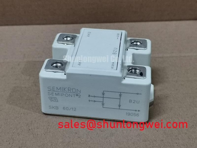
Where the rectifier is paired with an upstream controlled conversion stage, the SKB 30/12 A1 can be reviewed as a related component reference. It should not be treated as a prescribed companion or automatic substitute for the MP5005W-BP. The system designer must verify topology, voltage class, current path, terminal layout, and protection requirements independently.
Firing Delay and AC to DC Conversion Checks
Firing-angle changes in a controlled AC-to-DC converter alter conduction intervals, input current shape, power factor, reactive demand, and the stress seen by the rectifier stage. The MP5005W-BP is an uncontrolled diode bridge; firing-angle control applies to separate controlled devices in the system. Its 50.0 V repetitive peak reverse-voltage rating must be checked against peak reverse stress, including transients, while its 50.0 A average forward rectified current rating must be assessed under the applicable thermal and waveform conditions. These ratings do not, by themselves, define an allowable firing-angle range for a particular furnace controller.
During a commissioning fault, record the controller’s firing command, transformer secondary waveform, bridge terminal waveform, DC output behavior, and load response together. A delayed or uneven conduction pattern may involve gate timing in the controlled stage, synchronization, transformer leakage, control-loop behavior, protection interlocks, or a damaged power device. The diagnostic task is to compare the affected channel with the known-good signal path and identify where the waveform first diverges.
Dead-time and interlock behavior should be verified at the controller and driver level when a controlled converter shares a DC link with regenerative braking or high-power braking resistance. The required timing is system-determined by switching devices, driver propagation, transformer behavior, and measured turn-off recovery. Designers should minimize unintended overlap and validate the resulting peak voltage and current during controlled tests.
High-frequency auxiliary supplies also deserve attention. Where bootstrap-powered gate drivers are used, bootstrap capacitors and their charging diodes must maintain the driver supply throughout the intended switching sequence, while diode recovery and common-mode transients can disturb isolated control signals. For industrial drive boards, optical or digital isolation should be checked against the actual common-mode transient environment rather than assumed from the bridge rating. The Power Electronics Masterclass provides additional system-level reference material for power-stage evaluation, while the Vienna rectifier topology reference illustrates how rectifier topology affects current paths and power-factor behavior.