
Content last revised on September 10, 2026
Mitsubishi RM60DZ-H Diode Module Analysis
Thermal Dissipation and Isolation in Industrial Rectification
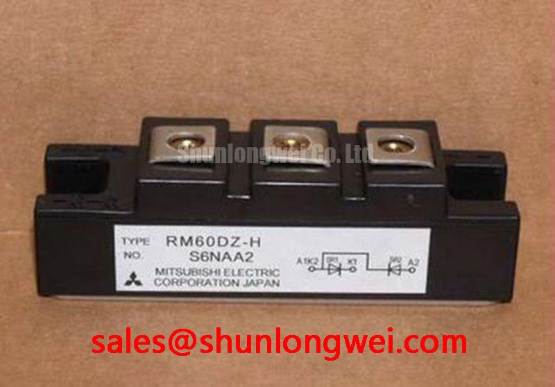
The Mitsubishi RM60DZ-H is a high-durability rectifier module designed to provide efficient thermal dissipation and high electrical isolation in medium-power industrial converters. Rated at 800V and 60A, this dual-diode module features a double arm configuration in an insulated package. By offering a high surge current tolerance of 1200A and a low forward voltage drop of 1.25V, it reduces thermal accumulation and housing footprints. The unit provides an isolation voltage rating of 2500V AC, which directly addresses insulation requirements in motor control setups. What does the 2500V isolation voltage enable? Safe direct mounting to a common heatsink without requiring extra thermal pads.
Application Scenarios & Value
Optimizing Power Converters and Motor Drives
For 400V industrial rectifier designs prioritizing thermal margin, this 800V module is the optimal choice. Engineers often face high-stress thermal environments when designing the mains rectifying stage of motor control systems. The RM60DZ-H diode module directly addresses these integration hurdles by providing a double arm configuration on an insulated base. By integrating two rectifying elements in series, the module functions cleanly as one leg of a three-phase input bridge, simplifying the physical layout of the inverter DC bus. The structural insulation allows designers to mount multiple units directly to a single metal block without compromising safety. When configuring a surge protection circuit, engineers must check the current and voltage criteria of the rectifier to prevent avalanche breakdown. While this 60A module serves standard drives, for high-capacity systems requiring greater current headroom, the related RM100DZ-H supports an average current of 100A.
Technical & Design Deep Dive
Analyzing Thermal Performance and Electrical Isolation Boundaries
Thermal management is the main limiting factor in rectifier design. The RM60DZ-H addresses this through a robust mechanical design where heat transfer occurs across an insulated ceramic substrate. To understand the thermal limits, engineers perform thermal resistance optimization calculations by measuring heat flow from the silicon junction to the heatsink surface. What is the primary benefit of its double-arm design? Simplifies wiring and circuit layout by integrating two diodes in series.
The electrical and physical parameters of this module demonstrate its suitability for harsh environments. For instance, the isolation voltage (Viso = 2500V) rating acts like a thick firewall separating a high-security zone from a public lobby, ensuring the electrical path remains completely decoupled from the chassis metal. Additionally, the peak surge current (IFSM = 1200A) represents a vital safety margin. Like a structural levee designed to withstand a once-in-a-decade flash flood without breaching, this 1200A surge current rating protects the module against short-term electrical surges. Designers can execute accurate datasheet verification to align these transient peak currents with upstream circuit breakers and fuses. The junction temperature range (Tj) spans from -40°C to +150°C, providing the required operating margin during transient overload states.
Key Parameter Overview
Decoding the Specs for Enhanced Thermal Reliability
The following table lists the critical electrical and thermal limits of the RM60DZ-H module as derived from the manufacturer's engineering specifications.
| Parameter | Symbol | Rating | Unit | Condition / Description |
|---|---|---|---|---|
| Repetitive Peak Reverse Voltage | VRRM | 800 | V | Max peak voltage in reverse bias |
| Average Forward Current | IF(AV) | 60 | A | Single phase, half wave 180° conduction |
| Surge Forward Current | IFSM | 1200 | A | One half cycle, 60Hz peak value |
| Peak Forward Voltage | VF | 1.25 | V | Measured at peak current |
| Isolation Voltage | Viso | 2500 | V AC | Charged part to case, 1 minute |
| Junction Temperature | Tj | -40 to +150 | °C | Operational range for silicon chip |
Download the RM60DZ-H datasheet for detailed specifications and performance curves.
Frequently Asked Questions
Addressing Core Integration and Testing Challenges
How does the integrated 2500V AC isolation impact heatsink assembly and overall system layout?
The built-in isolation ensures the active diode elements are electrically separated from the metal baseplate. This allows direct installation to a shared metal chassis or heatsink without using mica washers or silicone pads, minimizing interface thermal resistance.
What is the maximum forward voltage (VF) at 60A and how does it determine thermal design?
The maximum forward voltage is 1.25V. Conduction loss is calculated by multiplying this voltage by the operating current, which serves as the baseline for determining the required cooling capacity and verifying the safe operating limits.
How can an engineer verify the health of the RM60DZ-H module using a standard multimeter?
Set the multimeter to diode test mode. Check the forward bias voltage (should read around 0.4V to 0.7V) and reverse bias isolation (should read open circuit) across both diode arms to confirm element integrity.
Navigating component lifecycle changes in industrial automation requires verified technical data. Access to reliable rectifier modules ensures long-term operational continuity for existing drive infrastructures.