


Content last revised on September 24, 2026
1DI50MA-050 Operational Boundaries: Evaluating Baseplate Convexity Compensation and Screw Limits
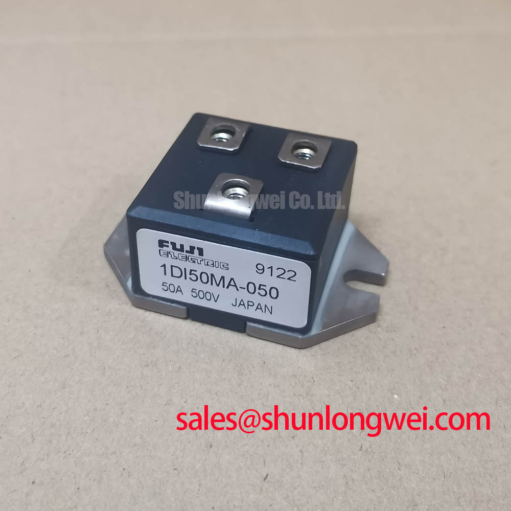
Before mounting, verify the nameplate against the repair record and use a meter in diode mode to compare the cold-state terminal paths with the known circuit topology. The 1DI50MA-050 from Fuji Electric is a Power Diode Module specified with a 2500V voltage rating and a 50A current rating under the applicable datasheet conditions. Confirm terminal polarity, isolation from the baseplate where applicable to the equipment design, and the absence of unintended low-resistance paths before reconnecting power wiring. Fuji Electric’s broader module portfolio can be reviewed through its power semiconductor and IPM modules page.
The module-to-heatsink joint should be checked as a mechanical interface, not treated as a cosmetic installation detail. A straightedge and suitable inspection method can reveal local heatsink damage, debris, or unevenness that can prevent uniform contact beneath the module baseplate. These conditions may create localized thermal stress during cyclic loading, even when the external hardware appears secure.
As a Design Consideration, thermal interface material should be applied as a controlled, continuous thin layer. A typical interface thickness range of 50–100 μm is a general integration reference rather than an official parameter for this model. The actual material, surface finish, pressure distribution, and permissible thickness must be validated by the equipment designer. Where baseplate curvature or heatsink flatness is uncertain, inspect the transferred contact pattern after a controlled trial fit rather than compensating with excessive compound.
Install mounting screws in a gradual cross-pattern sequence so contact pressure develops evenly across the module footprint. The applicable torque must come from the original equipment documentation and the hardware specification; it must not be inferred from the module current rating. ⚠️ Field Alert: Do not fully tighten one mounting point before the remaining screws have engaged, because uneven clamp loading can distort the thermal interface.
For a heavy-duty variable-frequency AC motor drive repair, preserve clearance around power terminals and avoid routing sensitive control conductors alongside high-current commutation paths. This is a Design Consideration intended to reduce coupling into sensitive wiring. If the original assembly requires a related module assessment, QM100HY-2H can be reviewed as a separate compatibility candidate; its terminal arrangement, electrical limits, thermal interface, and application requirements require independent verification.
Field Diagnostics & Commissioning: Transient Thermal Impedance in 1DI50MA-050 Topologies
During pulsed-load commissioning, case temperature alone does not establish junction temperature. Junction-to-case transient response depends on pulse duration, repetition pattern, loss distribution, and the thermal path into the heatsink. An Engineering Calculation using the applicable manufacturer thermal model can estimate junction excursion by combining measured or calculated device loss with the time-dependent thermal impedance. The resulting estimate should be checked against the model’s published operating boundaries and the actual cooling conditions.
Where no verified model data are available for the installed assembly, trend objective measurements instead: case temperature behavior, heatsink response, phase current, DC-link waveform, and switching-node behavior. A rising thermal response under unchanged load can indicate several possibilities, including degraded interface contact, airflow changes, altered commutation conditions, or a control issue. It should be investigated against a known-good waveform and thermal baseline rather than assigned to one cause.
Reverse-recovery behavior can contribute to current transients and ringing in converter legs. Snubber selection and loop layout are system-level matters. As a Design Consideration, minimize the commutation-loop inductance to limit voltage overshoot, then verify voltage peaks during switching tests against the DC-link condition and the module’s 2500V voltage rating. In a wider drive power chain, the 7MBR50SA120-50 is a related power-module reference for separate topology and interface evaluation.
💡 Bench Tip: Use ESD-controlled handling and record cold-state diode-mode readings before energizing, then compare any later readings only with the same meter polarity and test setup.
Field Diagnostics & Commissioning: Dynamic Commutation Control for Robust 1DI50MA-050 Topologies
Power-terminal and commutation behavior must be validated at the module terminals, not only at the converter or driver-board connection. Long conductors, shared return paths, and power-loop magnetic fields can alter the voltage and current transients seen during diode recovery. Ringing or an unexpected voltage excursion during the opposite device transition may indicate coupling that warrants oscilloscope verification with an appropriate probing method.
Controlled commutation, suitable snubbering, and careful busbar layout are Design Considerations used in some high-energy converter designs to limit recovery-related overvoltage and ringing. A negative gate-bias range of −5V to −15V is not applicable as a direct operating instruction for the 1DI50MA-050, which is a diode module without a gate terminal. Any associated switching-device drive voltage, clamp threshold, external resistance, isolation arrangement, and timing must be selected from verified documentation for the complete converter.
During commissioning, compare diode forward-current behavior, reverse-voltage switching waveforms, current direction, and the converter’s dead-time strategy under controlled conditions. Do not change commutation or snubber components in isolation: a slower transition can reduce ringing while increasing switching loss, and the acceptable balance is determined by the system’s measured thermal and voltage margins.
Transient Dynamics & Electrical Design: High-Speed Fault Management and Reverse-Recovery Overvoltage in 1DI50MA-050
Fault and overvoltage protection should be assessed as part of the complete power path. A protection circuit may monitor abnormal current or voltage conditions, but the detection threshold, blanking interval, sensing network, and fault response must match the actual topology and verified safe-operating information. References to Type I or Type II short-circuit behavior and response times below 10 μs are system protection concepts, not official performance claims for this module without the applicable Fuji Electric data.
Controlled fault interruption and voltage clamping are Design Considerations when diode recovery or a sudden current interruption could create excessive inductive overvoltage. The protection circuit should be evaluated with real busbar inductance, load current, DC-link condition, and measured reverse-voltage peak. Fast semiconductor fuses also require a coordinated assessment of their published I²t characteristics and the converter’s prospective fault current; no fuse selection can be established from the module’s 50A current rating alone.
For integration guidance on power-module interfaces, thermal management, and switching-loop management, consult IGBT Design & Integration. Additional manufacturer product-family context is available through the Fuji Electric power semiconductor portal.