Content last revised on September 10, 2026
Field Diagnostics & Commissioning: Baseplate Thermal Grease Layer Control in 5SNG015045P0301 Topologies
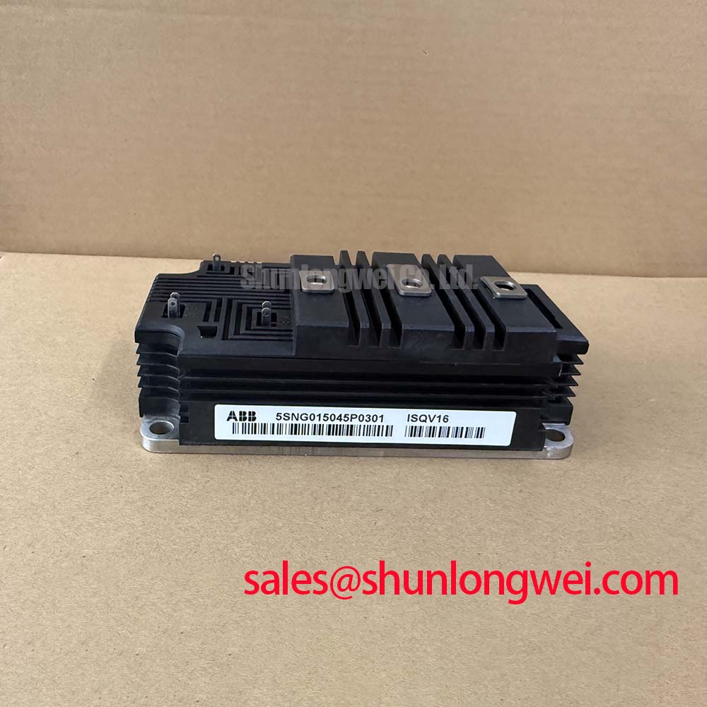
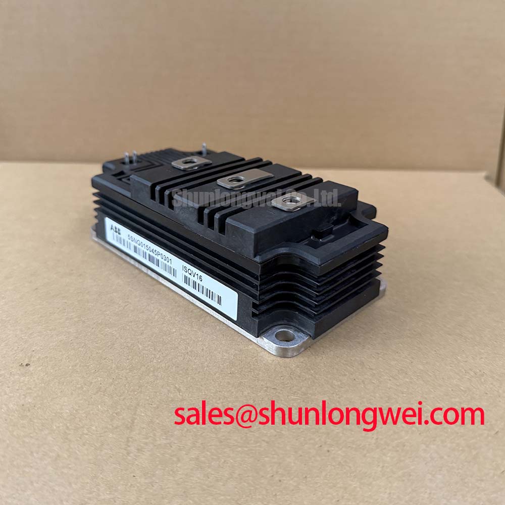
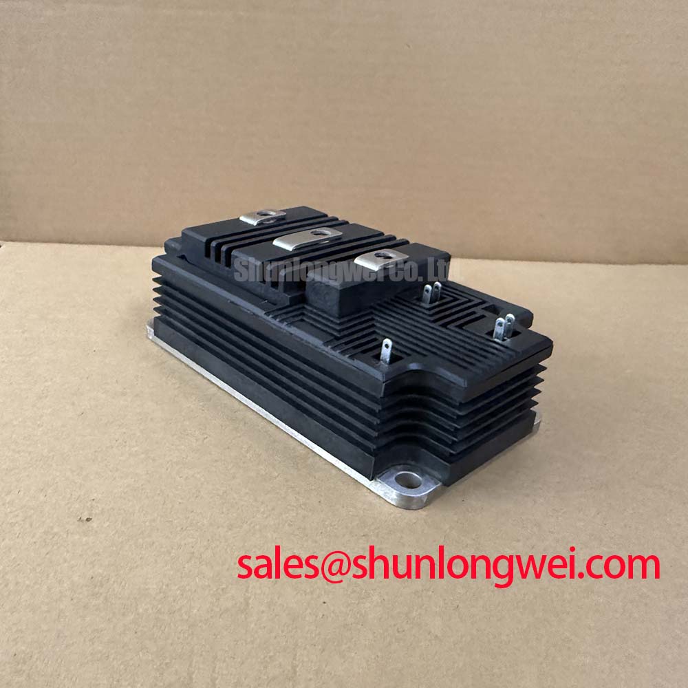
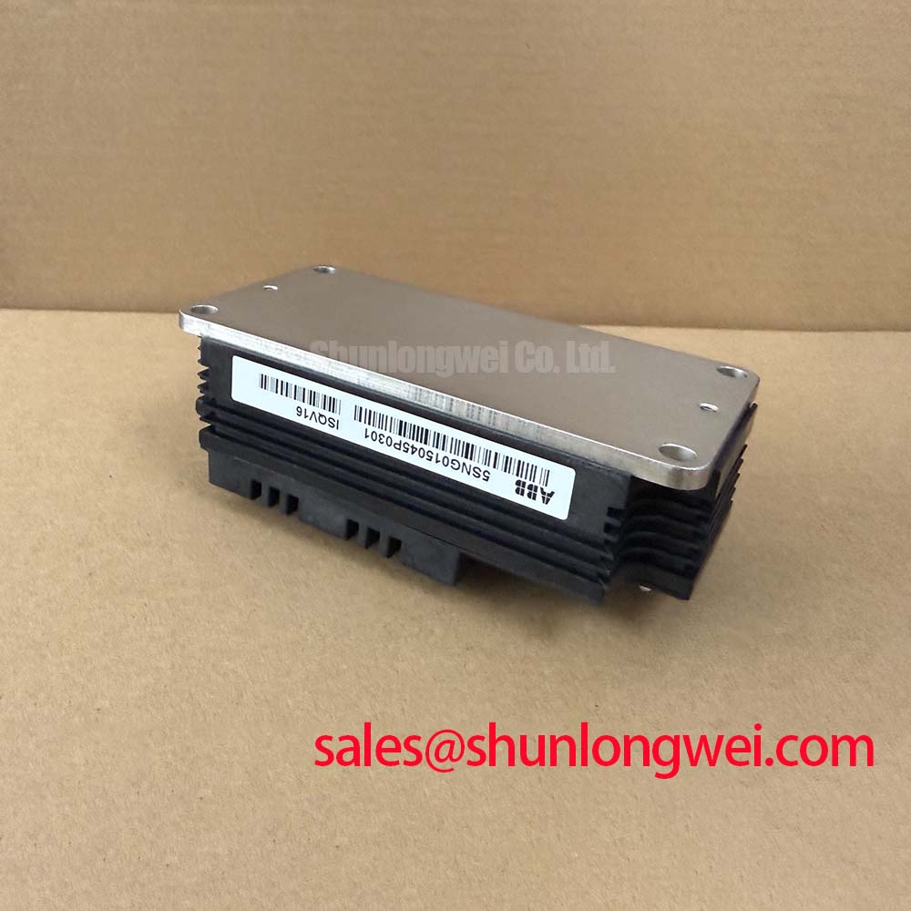
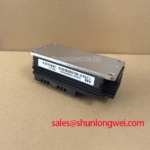
Before connecting a replacement unit, isolate the converter, confirm discharged DC-link conditions, inspect the terminal interfaces, and verify that the nameplate identifies ABB 5SNG015045P0301. This HiPak IGBT module is officially specified at VCES = 4500 V and IC = 150 A. Its stated gate-emitter threshold range is 5.4 V to 6.4 V; that value is an official threshold specification, not a gate-drive supply recommendation.
A clean baseplate and heatsink contact area are essential during commissioning. As a Design Consideration, apply thermal interface material as a controlled, continuous layer, commonly within a 50 to 100 um assembly target where the approved material and mating surfaces support that process. The objective is to fill surface irregularities without creating a thick insulating layer. Check for trapped debris, dried compound, edge voids, or evidence that the heatsink face is not planar. Baseplate curvature and heatsink flatness should be evaluated together rather than treated as separate conditions.
Install mounting hardware in a staged cross-pattern sequence so clamp load develops evenly across the module. The final torque, screw grade, washer arrangement, and thermal compound must follow the equipment documentation and the approved mechanical assembly process. Bench Tip: Disconnect gate-drive cables only after stored energy has been discharged, then compare cold-state terminal readings with the removed circuit documentation or a known-good assembly.
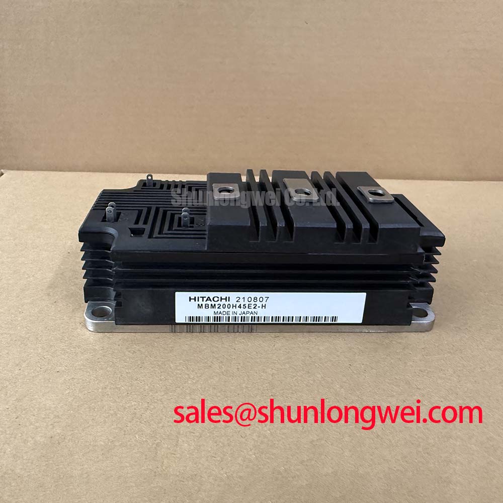
For repairs where an alternative device is being evaluated, terminal layout, insulation arrangement, thermal interface, driver compatibility, and protection behavior must all be verified before substitution. The MBM200H45E2-H can be reviewed as a separate compatible-device evaluation candidate, but it is not an automatic replacement for this ABB module.
Field Diagnostics & Commissioning: SCSOA Overcurrent Protection: Implementing in 5SNG015045P0301 Topologies
The protection circuit should be checked as a complete path: current sensing, fault comparator or controller logic, gate-driver response, interlock, and recorded shutdown waveform. The supplied official parameters identify this module’s voltage, current, threshold, package family, and isolation rating, but do not provide an SCSOA curve or a permitted short-circuit duration. System engineers should therefore obtain the applicable manufacturer documentation before assigning a short-circuit withstand limit or a protection delay.
As a Design Consideration, overcurrent detection should initiate a controlled gate shutdown appropriate to the measured switching loop and DC-link conditions. A two-stage soft turn-off strategy is often evaluated where abrupt interruption of fault current could create an unacceptable inductive overshoot. Its resistor values, timing, and clamping arrangement are system-determined and require switching tests that verify collector-emitter peak voltage against the DC-link operating condition.
Complementary switching commands need a deliberate interlock so a command transition cannot create shoot-through. Dead-time is not a fixed module parameter; it depends on the actual gate driver, gate network, switching temperature, propagation mismatch, and measured turn-on and turn-off behavior. During inspection, compare the commanded gate waveforms and collector-emitter response at the same operating point. A discrepancy may indicate driver-path asymmetry, an interlock issue, or a measurement-reference problem.
Isolation between the control domain and power domain is also part of this review. The module is officially specified for 6000 V AC for 1 minute isolation, while the system’s driver isolation implementation remains a separate design responsibility. Practical context on galvanic barriers is available from Galvanic Isolation Principles in High Voltage Power Systems. Where isolated current feedback is used, engineers can also compare applicable interface principles with Broadcom optically isolated amplifiers and current sensors.
Preventing Spurious Faults: DC-Bus Operating Voltage Headroom Derating Guidelines for 5SNG015045P0301
The 4500 V VCES rating is an Official Datasheet Specification and establishes the module’s blocking-voltage identity. It does not by itself establish an allowable DC-bus setting, surge margin, altitude policy, or lifetime prediction. For commercial string inverter and micro-grid energy-storage evaluations, measure the DC-link at the module terminals and capture switching transients under representative loading, regeneration, and fault-clearing conditions.
DC-bus headroom should be evaluated using the complete system: nominal source range, control response, cable and busbar inductance, snubber condition, temperature, and switching waveform. Minimize parasitic loop inductance to suppress turn-off inductive overshoots, then verify peak margins through instrumented switching tests. A recurring driver trip or voltage alarm may indicate a control threshold, sensing path, transient, or grounding issue; it should not be assigned to one cause without waveform evidence.
Altitude and terrestrial neutron exposure are high-risk reliability subjects. No FIT rate, single-event burnout rate, or altitude derating value can be derived from the provided official specifications. As a Design Consideration, projects operating at elevated locations should request manufacturer guidance and apply the installation standard, insulation coordination study, and site conditions used for the complete converter. The practical test framework in The Ultimate IGBT Knowledge Base can support a structured review of switching measurements and protection evidence.
Transient Dynamics & Electrical Design: Dynamic Power Loss Dissipation and Multi-R on 5SNG015045P0301
For pulsed overload investigation, begin with measured current, collector-emitter voltage, gate waveform, heatsink condition, and event duration. The HiPak high-reliability package describes the official package classification, but the provided data does not include transient thermal impedance curves, junction-to-case resistance, switching-energy curves, or a maximum junction-temperature specification. Those values must come from the applicable ABB documentation before calculating junction temperature.
A multi-RC thermal model can represent the time-dependent path from semiconductor junction to case, provided its resistance and time-constant data are official and applicable to the exact device. In engineering terms, the model accumulates power losses across short and long thermal time constants, allowing the test team to estimate whether a pulse sequence approaches the permitted junction boundary. This is an Engineering Calculation only when supported by measured power loss and manufacturer thermal-model data.
When integrating the module, keep the gate loop controlled, maintain a low-inductance power layout, and verify gate-emitter behavior at the device terminals with correctly rated differential measurement equipment. The H2G150ND06M1 may be relevant when reviewing associated rectification or complementary power-stage positions, subject to a separate topology and rating check. Do not infer dynamic-loss capability, pulse overload tolerance, or parallel-current sharing from the 150 A continuous current rating alone.