

Content last revised on September 23, 2026
PF1000A-360 Product Identity and Verified Selection Data
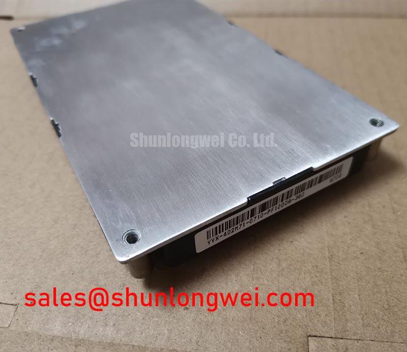
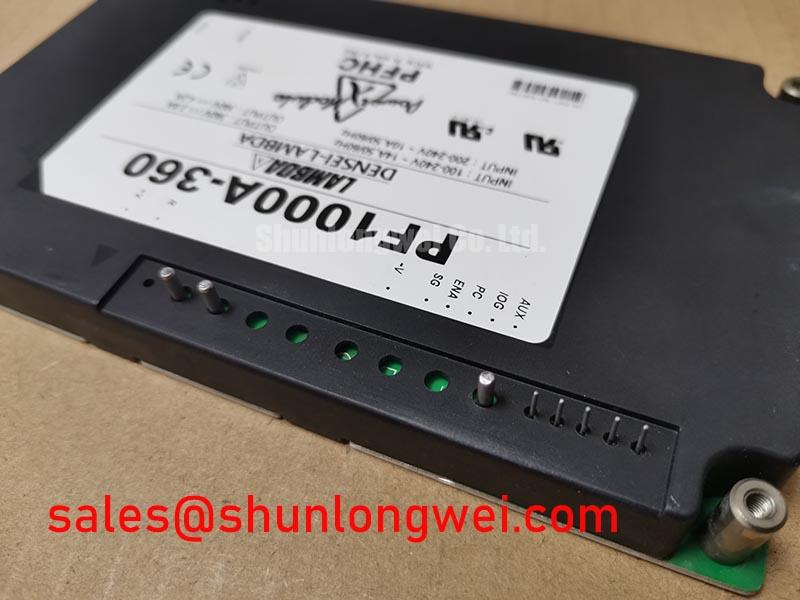
Begin field evaluation by checking the nameplate, connector condition, enclosure damage, and cold-state resistance against the original equipment documentation before applying power to the PF1000A-360. This part is identified for the supplied product record as a TDK-Lambda power supply and DC-DC converter module with a module-style enclosure.
The available factory parameter context identifies the operating voltage as Standard Industrial Rating, the rated current as Standard Operating Current, and the package as Module. No numeric voltage or current value is included in the supplied specification record. The system integrator should therefore verify the exact input, output, isolation, polarity, current, and protection requirements from the original equipment manual or the applicable manufacturer documentation before substitution.
| Model | PF1000A-360 |
| Manufacturer | TDK-Lambda |
| Product category | Power Supply / DC-DC Converter |
| Operating voltage | Standard Industrial Rating, numeric value to be verified |
| Rated current | Standard Operating Current, numeric value to be verified |
| Package | Module |
For procurement and repair records, retain the exact model marking, equipment position, connector orientation, and original wiring photographs. These details are important when evaluating a replacement power module in an industrial inverter welder or a medium-frequency induction heating power supply. A module category alone does not confirm electrical interchangeability.
Transient Dynamics and Electrical Design for Industrial Converter Integration
When integrating the PF1000A-360 into an inverter welder or induction heating system, the first design task is to confirm the converter’s actual electrical role in the equipment topology. It may be associated with a control supply, an isolated auxiliary rail, a gate-drive supply, or another subsystem, but the supplied product data does not identify a specific output voltage, current limit, switching frequency, or isolation rating. Designers should verify those values from the original system documentation rather than infer them from the model name.
Gate-drive dead time, enable sequencing, undervoltage lockout behavior, and control-board startup timing should be checked at system level when this module supplies a switching stage. An incorrect sequence can leave a gate driver partially active while its control logic is still initializing. Use a differential probe and an isolated measurement method to compare the power rail, enable signal, and switching-node response during startup and shutdown. The target is controlled sequencing with no unintended overlap, rather than a fixed timing value assumed without a confirmed datasheet.
For a power stage using multiple switching devices, symmetrical gate-loop routing remains a Design Consideration. Equal conductor paths, consistent return routing, and controlled common impedance help reduce dynamic imbalance. The positive temperature coefficient of a transistor’s saturation voltage can support static current sharing in suitable parallel arrangements, but it does not remove the need to verify switching behavior, gate resistance, stray inductance, and thermal distribution on the actual assembly.
Long motor cables can produce transmission-line reflections and elevated voltage at the motor terminals. In an industrial inverter welder or induction heating platform, designers should assess cable length, impedance, switching edge rate, shield termination, and the location of any output filter. The PF1000A-360 should not be assigned a filtering function unless the equipment documentation confirms that role. Oscilloscope testing at the converter output and at the downstream load can help distinguish a supply transient from a power-stage or cable-reflection event.
When the system includes a regenerative braking chopper, the braking resistor and its control path must be evaluated separately from the auxiliary converter. Confirm the resistor’s thermal duty, switching threshold, wiring inductance, and fault response using the equipment design data. In a bidirectional DC-DC battery system, charge and discharge cycling also require separate assessment of current limits, thermal paths, control stability, and battery protection. These are system-level conditions, not confirmed characteristics of the PF1000A-360.
For a neutral comparison point within a broader power semiconductor assembly, engineers may review the MG150Q1JS40. It should be treated as a separate component record, not as an automatic substitute for the PF1000A-360. Pin arrangement, electrical ratings, control requirements, mechanical fit, and thermal behavior must be matched before any cross-reference is considered.
Field Diagnostics and Commissioning: Thermal Contact and Power-Rail Stability
Commissioning should start with a visual inspection of the module mounting surface, fasteners, terminal hardware, insulators, and surrounding airflow path. Remove dust from the heatsink and check whether the cooling path is restricted by cable bundles, filters, or accumulated debris. A clean mechanical interface is especially important when the module operates continuously inside a compact welder or induction heating cabinet.
Thermal interface material should be applied as a controlled, continuous layer suitable for the actual module base and heatsink finish. The supplied factory information does not specify TIM thickness, baseplate flatness, mounting torque, or screw sequence for this model, so those values must come from the applicable mechanical documentation. As a Design Consideration, technicians should avoid trapped air, uneven pressure, contamination, and excessive compound that can migrate toward terminals or insulating surfaces.
Sequential tightening is commonly used to distribute contact pressure across a module base, but the correct pattern and torque remain manufacturer and assembly dependent. After commissioning, compare the temperature at the module mounting region, heatsink inlet and outlet, terminals, and nearby capacitors under a controlled load. A rising terminal temperature or uneven thermal pattern may indicate contact resistance, airflow imbalance, loose hardware, or an overloaded subsystem; confirm the finding with de-energized resistance checks and current measurements.
⚠️ Maintenance Note: Schedule heatsink cleaning and contact-temperature checks as part of preventive maintenance, and inspect for condensation after cold starts or cabinet door opening in humid areas.
Parasitic busbar inductance should be minimized where the PF1000A-360 is positioned close to a fast switching stage, with the final layout validated by measured overshoot against the equipment’s DC-link boundary. A snubber film capacitor, when required by the switching topology, should be placed according to the high-current commutation loop rather than at an electrically convenient but remote location. Component voltage, pulse current, RMS heating, and lifetime must be verified from the complete switching waveform.
If the module supports a control rail, record the rail during no-load startup, normal load, peak load, shutdown, and fault recovery. Ripple, dropout, delayed enable, and repeated restart behavior can originate in the load, wiring, control logic, or protection circuit. Compare measurements with a known-good unit or the equipment service record instead of assigning a single cause from one voltage reading.
The upstream rectifier and related conversion stage should also be checked when the auxiliary rail is unstable. The MG75H6EL1 may be reviewed as a separate rectifier or complementary-stage reference in the equipment topology, subject to confirmed ratings and wiring. It is not presented as a specified replacement for the PF1000A-360.
High-Altitude and Environmental Fault Evaluation
Altitude, cabinet pressure, humidity, dust, and cooling performance can change the operating margin of a complete power converter. The supplied PF1000A-360 data does not provide a high-altitude derating curve, cosmic-ray susceptibility result, Single Event Burnout data, FIT rate, insulation coordination table, or lifetime prediction. No numerical SEB probability or operating-life claim should therefore be assigned to this product record.
For equipment installed above the manufacturer’s stated environmental range, the system engineer should obtain the applicable altitude and insulation requirements, then verify creepage, clearance, thermal dissipation, dielectric stress, and cooling capacity under the real installation conditions. This is a Design Consideration, not an official PF1000A-360 derating specification. Field investigation should document the installation altitude, enclosure sealing, internal temperature, condensation history, DC-link behavior, and the time relationship between load events and faults.
Partial discharge testing may be relevant when high-voltage insulation, encapsulated assemblies, or contaminated surfaces are involved. The subject should be handled with appropriate test equipment and documented acceptance criteria; general background is available through Partial Discharge Detection in High Voltage Power Modules. A module cannot be declared compliant with a complete equipment insulation or EMC requirement solely from its component identity.
For reliability documentation and test-method selection, engineers can consult the JEDEC Solid State Technology Association Standards. Any FIT, SEB, cosmic-ray, or life estimate must be tied to a cited test method, defined mission profile, and authoritative data source. Without that evidence, troubleshooting should remain focused on measurable voltage stress, current transients, thermal conditions, insulation condition, and assembly workmanship.
Thermal interface behavior and cooling architecture can also be reviewed in The Advanced Thermal Management Revolution. The reference can support maintenance planning and thermal-test preparation, but it does not establish a PF1000A-360-specific construction or cooling rating.
High-Speed Fault Management and Desaturation Protection
Before applying full bus voltage, verify the protection chain from fault sensing to gate-driver shutdown, including signal polarity, isolation, reset behavior, and the response of the downstream power stage. The supplied product information does not confirm a desaturation threshold, short-circuit withstand time, SCSOA limit, or Type I or Type II protection classification for the PF1000A-360. Those values must be confirmed from the relevant driver and power-stage documentation.
A desaturation circuit can indicate that a switching device is not entering its expected conduction state, but the signal may also be affected by blanking behavior, diode recovery, layout coupling, probe capacitance, or an incorrectly routed sense path. Validate the signal with a suitable differential probe and compare it with gate voltage, collector-emitter voltage, load current, and the driver’s fault output. A single fault indication should not be treated as proof of one failed component without checking the surrounding timing and wiring.
Two-stage soft turn-off is an Engineering Recommendation that may help limit inductive overshoot when a short-circuit event is detected. The actual sequence, gate-current profile, clamp behavior, and shutdown duration must be determined by the gate driver, switching device, DC-link layout, and measured peak voltage. Designers should minimize the commutation loop and confirm the resulting peak margins during controlled switching tests rather than applying an assumed universal microsecond value.
During fault commissioning, use reduced energy and a controlled current limit where permitted by the equipment procedure. Capture the first fault event, because repeated restart attempts can alter thermal conditions and obscure the original trigger. Check gate-drive supply stability, dead-time operation, auxiliary converter behavior, current-transformer or shunt signals, snubber condition, and cable termination before returning the equipment to service.