Content last revised on October 24, 2026
FF200R33KF2 Operational Boundaries: Evaluating Torque Reaction Absorption and Preventing Terminal Stress
Manufacturer: Infineon | Category: IGBT Module | Voltage Rating: 3300 V VCES | Current Rating: 200 A at TC = 80°C
Check the main power terminal hardware before applying electrical stress. The FF200R33KF2 is rated at VCES = 3300 V and IC = 200 A at TC = 80°C; these electrical limits do not compensate for mechanical loading transferred through the terminals.
During replacement, inspect thread engagement, washer seating, busbar alignment, and the direction of cable or laminated-busbar force. A misaligned conductor can apply levering stress to internal copper joints when the enclosure vibrates or the assembly expands during thermal cycling. Keep the power connection naturally aligned with the terminal axis, and prevent the busbar from pulling sideways while the fastener is tightened.
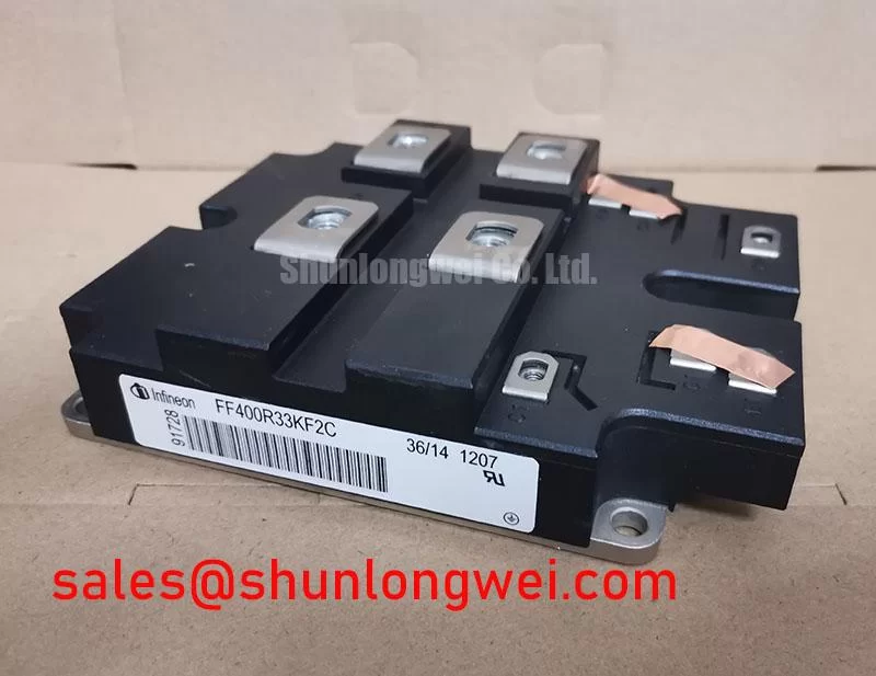
Use a calibrated torque tool and the fastening specification issued for the actual module hardware and busbar assembly. Do not substitute a torque value from a visually similar package. If the terminal rotates, the washer does not sit flat, or the busbar springs away after tightening, stop the installation and correct the mechanical stack-up. The neutral FF400R33KF2 page can be reviewed when comparing current replacement requirements, but electrical and mechanical compatibility remain system-level checks.
FF200R33KF2 Thermal-Electrical Optimization: Mitigating Hard-Switching Transients Through Practical Tuning
Short-circuit protection should be coordinated with the gate driver, desaturation sensing, gate discharge path, and the measured switching loop. A design that targets Type I or Type II short-circuit detection within a sub-10 µs response window must validate the complete protection chain; that timing is a system design target, not an official rating stated in the supplied FF200R33KF2 parameters.
Two-stage soft turn-off can be evaluated as an engineering recommendation when the driver must limit the interaction between fault current decay and stray inductance. The first action should recognize the fault without creating unnecessary gate disturbance, while the controlled turn-off stage should be tuned against measured collector-emitter overshoot. The module’s ±20 V VGES rating defines the gate-emitter voltage boundary, but it does not prescribe a gate resistor, clamp voltage, or protection delay.
Confirm collector, emitter, and gate connections against the approved circuit drawing before energizing the inverter. Keep the gate return physically associated with its driver return, and route parallel power paths symmetrically where multiple modules are used. Creepage and clearance must be assessed against the actual working voltage, pollution environment, insulation system, and applicable equipment standard. For broader switching and protection principles, consult The Ultimate IGBT Knowledge Base.
FF200R33KF2 Circuit Protection and Reliability: Calibrating Baseplate Flatness
Thermal performance depends on the mechanical interface between the module baseplate, thermal interface material, and heatsink. The official maximum Rth(j-c) is 0.07 K/W per IGBT, so uneven contact can reduce the practical value of the specified junction-to-case thermal path.
Inspect the copper baseplate and heatsink for contamination, burrs, local distortion, and visible rocking before applying thermal material. A thin, continuous interface layer is a general installation consideration; a 50 to 80 µm target may be used only when the selected material and surface condition support that process, not as an FF200R33KF2 factory specification. Use diagonal, cross-pattern tightening to distribute pressure progressively and avoid bending the substrate.
After commissioning, compare temperatures across equivalent operating points and inspect the airflow path. The specified operating junction range is −40°C to +150°C. Maintenance Note: Monitor terminal and heatsink contact temperature during scheduled service and verify that dust accumulation has not restricted the cooling airflow.
Transient Dynamics and Electrical Design: Multi-Module Parallel Current Sharing with FF200R33KF2
Parallel operation requires matched power paths and closely balanced gate-loop geometry. The positive temperature behavior commonly associated with IGBT conduction can support steady-state static current sharing, but dynamic sharing is dominated by gate-loop impedance, emitter-path inductance, driver timing, and layout symmetry.
When integrating multiple FF200R33KF2 units, place equivalent conductors with comparable length and physical orientation. Confirm that each gate driver sees the intended reference potential, and inspect the turn-on and turn-off waveforms at the module terminals rather than relying on driver-board measurements alone. Switching imbalance may appear as unequal overshoot, different current rise behavior, or localized heating; correlate these observations with the complete busbar and gate wiring.
In a utility-scale 1500 V central solar photovoltaic inverter, this module may be evaluated within a high-power conversion stage subject to the inverter’s insulation, switching, cooling, and protection design. A preceding or complementary power stage may involve FS200R12PE4; that reference does not establish interchangeability. For intelligent-module system context, the Infineon CIPOS™ IPM product information should be treated as a separate product-family reference, while Infineon TRENCHSTOP™ IGBT7 describes related semiconductor technology rather than confirming an FF200R33KF2 construction detail.