
Content last revised on June 21, 2026
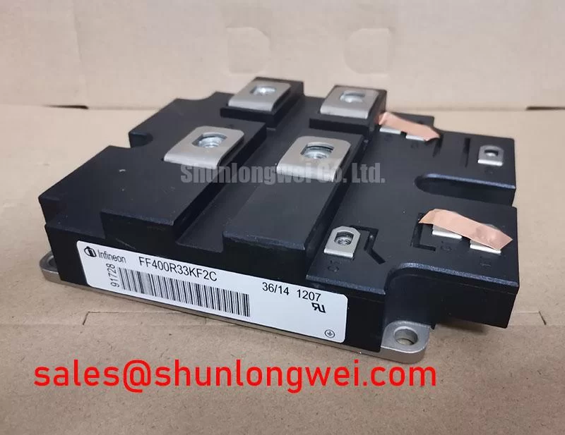
FF400R33KF2C: A High-Voltage IGBT Module Engineered for Demanding Power Systems
Engineering High-Reliability Power Conversion
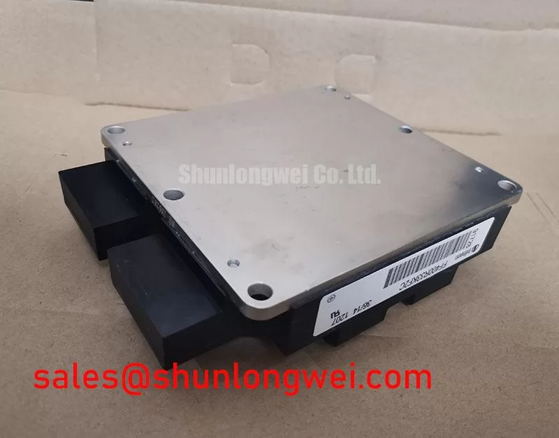
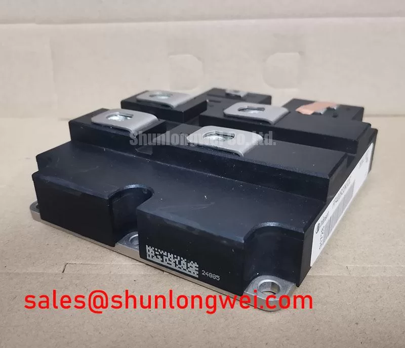
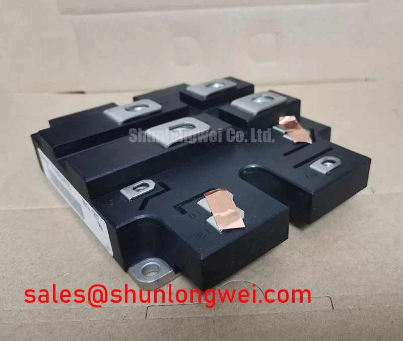
The Infineon FF400R33KF2C is a high-voltage dual IGBT module designed for robust performance in high-power industrial and traction applications. This module provides a formidable combination of high blocking voltage and substantial current handling, encapsulated in a large, industry-standard housing. With core specifications of 3300 V | 400 A | Tvj op -40°C to 125°C, it is engineered for exceptional thermal stability and electrical ruggedness. Key benefits include superior operational reliability under harsh conditions and a design optimized for medium-frequency switching. The FF400R33KF2C directly addresses the challenge of building dependable inverters for multi-megawatt systems by offering a high breakdown voltage, crucial for systems connected to medium-voltage grids. For high-power traction inverters and industrial drives requiring robust 3300V blocking capability, the FF400R33KF2C offers a proven and reliable solution.
Key Parameter Overview
Decoding the Specs for Enhanced Thermal Reliability
The technical specifications of the FF400R33KF2C are tailored for high-stress environments. The module's parameters underscore its capacity for stable, long-term operation. A low thermal resistance from junction to case is fundamental to effective heat dissipation, which is as critical as electrical ratings in high-power modules. Think of thermal resistance like the width of a highway; a lower value means a wider highway, allowing more "heat traffic" to flow away from the sensitive silicon chip, preventing overheating and extending the component's operational life.
| Parameter | Value | Conditions |
|---|---|---|
| Collector-Emitter Voltage (VCES) | 3300 V | Tvj = 25°C |
| Continuous DC Collector Current (IC) | 400 A | TC = 80°C, Tvj max = 150°C |
| Collector-Emitter Saturation Voltage (VCEsat) | 3.4 V (typ.) / 4.3 V (max.) | IC = 400 A, VGE = 15 V, Tvj = 25°C |
| Gate Threshold Voltage (VGE(th)) | 4.2 V (min.) / 5.8 V (typ.) / 7.4 V (max.) | IC = 16.0 mA, VCE = VGE, Tvj = 25°C |
| Thermal Resistance, Junction-to-Case (RthJC) per IGBT | 26.0 K/kW | - |
| Maximum Junction Temperature (Tvj max) | 150 °C | - |
| Operating Temperature (Tvj op) | -40°C to 125°C | Under switching conditions |
Download the FF400R33KF2C datasheet for detailed specifications and performance curves.
Application Scenarios & Value
System-Level Benefits in Traction and Industrial Drives
The FF400R33KF2C is specifically engineered for power conversion systems where high voltage and high reliability are non-negotiable. Its 3300V rating makes it an ideal candidate for inverters in medium-voltage applications, such as commercial and utility-scale renewable energy systems, industrial motor drives, and auxiliary converters in railway technology. A key engineering challenge in these systems is managing the high DC-link voltage while ensuring durability over a long service life. The module's high VCES provides the necessary safety margin against voltage overshoots that can occur during switching transients, a common issue in inductive-load applications like large motor drives. This robust voltage blocking capability simplifies the design of protective snubber circuits and enhances the overall system's resilience. For applications demanding even higher current, the related FZ800R33KF2C offers double the current rating within a similar voltage class.
Technical Deep Dive
A Closer Look at High-Voltage Design and Thermal Management
The performance of a high-voltage IGBT module like the FF400R33KF2C is not defined by its voltage rating alone. The interplay between its electrical characteristics and thermal performance is critical. The VCEsat of 3.4V (typical) at nominal current directly influences conduction losses—a primary source of heat. In a multi-megawatt inverter, even small improvements in VCEsat can lead to a significant reduction in waste heat, translating to lower heatsink costs, smaller enclosure sizes, and improved system-level efficiency. The maximum operating junction temperature of 125°C, coupled with its thermal resistance, dictates the module's power cycling capability. This is particularly important in applications like traction drives, which experience frequent start-stop cycles. A robust thermal design ensures the module can withstand these repeated thermal stresses without degradation, a cornerstone of long-term reliability in demanding field applications.
Frequently Asked Questions (FAQ)
What is the primary advantage of the 3300V VCES rating?
The 3300V collector-emitter voltage provides a significant safety margin for inverters operating on medium-voltage DC buses, typically seen in applications like 1500V DC solar inverters or traction systems, ensuring reliable operation even with voltage spikes.
How does the maximum collector-emitter saturation voltage (VCEsat) of 4.3V impact system design?
The VCEsat value is crucial for calculating conduction losses. Engineers must use this maximum value in their thermal models to design an adequate cooling system (heatsink and airflow) that keeps the IGBT junction temperature below the specified 125°C maximum under worst-case operating conditions.
Is this module suitable for high-frequency switching applications?
Given its voltage and current class, the FF400R33KF2C is optimized for low to medium switching frequencies, typically in the range of a few kilohertz. Its switching energy losses (Eon and Eoff) are significant, making it less ideal for high-frequency designs where switching losses would dominate and lead to excessive heat generation.
What does the dual-IGBT configuration enable?
The dual, or half-bridge, configuration is a fundamental building block for creating two-level or three-level inverters. It allows designers to construct one phase-leg of a three-phase inverter with a single module, simplifying the busbar layout and overall mechanical assembly of the power stack.
Strategic Considerations for High-Power System Design
Selecting a module like the FF400R33KF2C is a strategic decision for projects where long-term operational integrity and resilience to harsh electrical environments are paramount. Its established technology from Infineon provides a foundation of trust for engineers developing capital-intensive equipment like railway propulsion systems or large-scale industrial machinery. The focus on a high breakdown voltage and robust thermal characteristics over cutting-edge switching speed makes it a workhorse component, designed not for outright performance records but for steadfast, predictable operation over decades of service.