
Content last revised on September 10, 2026
Fuji Electric 6DI120A-060 Power Transistor Module: Incoming Inspection and Integration Notes
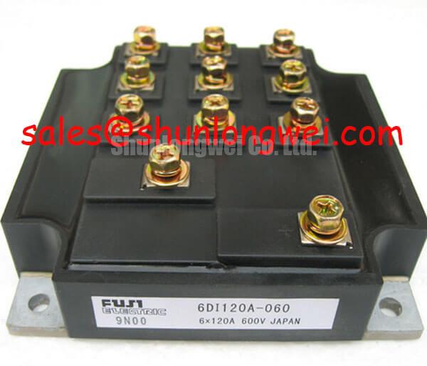
With the module fully isolated from the circuit, first inspect the case, terminals, markings, and mounting surface before checking cold-state terminal relationships with a calibrated multimeter. The documented product identity for 6DI120A-060 is a Fuji Electric Power Transistor Module rated at 600.0 V and 120.0 A. These values are Official Specification data supplied for this product page; they should not be treated as a complete operating envelope without the applicable Fuji Electric datasheet and system conditions.
For incoming QA, record the module marking and compare the terminal arrangement with the original equipment documentation. A diode-test reading can help identify expected semiconductor junction behavior, but the measured forward voltage depends on test current, temperature, meter design, and the internal circuit topology. It should therefore be used as a cold-state comparison against an approved reference unit rather than as an invented pass or fail threshold.
💡 Bench Tip: Use ESD protection, discharge the surrounding DC link, and compare all cold-state measurements with a known-good reference before applying any powered test.
Transient Dynamics and Electrical Design for 6DI120A-060
During replacement in a commercial string inverter or micro-grid energy-storage converter, confirm the complete gate-drive topology before energizing the module. The available product information verifies the voltage, current, and package category, but it does not verify a reinforced galvanic isolation rating, a specific common-mode transient immunity value, or a guaranteed gate-driver interface. Those characteristics belong to the selected driver, isolation barrier, PCB layout, and complete switching assembly rather than being inferred from the module name.
Minimize the high-current commutation loop and keep gate-drive return paths controlled to reduce parasitic inductive overshoot and common-mode ground bounce. The DC-link busbar, switching terminals, snubber or MOV network, and gate-driver wiring should be reviewed as one physical circuit. Designers should measure collector-emitter overshoot, gate-emitter ringing, and driver ground movement with suitable differential and isolated probing, then verify the peak stress against the module’s documented electrical limits under the actual switching conditions.
For an application review, the manufacturer’s Fuji Electric Power Semiconductor and IPM Modules information provides useful product-family context. It does not replace the exact datasheet for 6DI120A-060. If an inverter control board uses isolated gate supplies, the system integrator should verify creepage, clearance, isolation test conditions, and common-mode behavior from the driver documentation and safety design file.
Assembly Integrity and Gate-Voltage Noise Control
High dv/dt can couple into a gate circuit through parasitic capacitance and may produce unwanted gate movement if the driver loop is poorly referenced. An active Miller clamp, negative turn-off bias, ferrite treatment, or gate resistor network may be considered only after the actual gate-drive schematic and waveform evidence have been reviewed. The requested negative-bias range and a sub-microsecond desaturation response are not documented Official Specifications for this product, so they should not be presented as mandatory settings for 6DI120A-060.
At the bench, monitor the gate-emitter waveform directly at the module terminals while observing the collector-emitter transition. Look for false pulses, excessive ringing, unequal switching between parallel paths, and abnormal delay during fault turn-off. A desaturation protection circuit, if used by the system, should be evaluated for blanking behavior, current-sense accuracy, soft turn-off interaction, and fault-latch recovery. The final timing is system-determined and must be validated against the driver, load, bus voltage, and short-circuit test procedure.
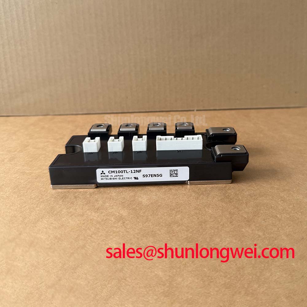
Do not apply thyristor gate parameters such as IGT and VGT as acceptance criteria for this transistor module. Those terms describe thyristor triggering and are relevant only if a separate thyristor stage exists in the equipment. For comparison during procurement review, engineers may examine the neutral product information for 6MBP100TEA060-50, while confirming interchangeability from the electrical ratings, terminal layout, mechanical envelope, gate requirements, and protection design.
Thermal and Electrical Integration at the Baseplate
The Power Transistor Module package should be mounted on a clean, flat heatsink with a thermal interface selected for the equipment’s insulation, pressure, temperature, and service requirements. The supplied product data does not specify thermal resistance, baseplate flatness, allowable mounting torque, or an approved thermal compound thickness. These values must come from the applicable manufacturer documentation, the thermal-interface supplier, or the equipment assembly specification.
During installation, remove particles and old compound from both mating surfaces, apply the interface material consistently, and tighten the fasteners progressively so the module is not forced into uneven mechanical stress. Inspect the contact imprint after a controlled trial assembly where the repair process permits it. Excess compound can increase thermal resistance, while incomplete coverage can create localized heating; the correct amount is determined by the surface condition and interface material, not by a universal thickness claim.
For parallel switching devices, positive temperature behavior may support current sharing, but static and dynamic balance still depend on matched drive paths, symmetrical busbar geometry, emitter or source layout, device temperature, and switching tolerances. Engineers should verify current distribution with appropriate probes under representative load conditions. The 600.0 V and 120.0 A ratings identify the product’s stated electrical class; they do not independently establish a permissible inverter bus voltage, switching frequency, overload duration, or parallel-device count.
Benchtop Waveform Tuning and Reliability Boundaries
Before returning a repaired inverter to service, capture the switching waveform at controlled voltage and load conditions, then inspect the turn-off peak, gate disturbance, ringing, and thermal response. A MOV or related overvoltage network should be coordinated with the DC-link architecture and switching transient energy. Its clamping behavior, pulse capability, aging characteristics, and placement require system-level verification rather than a fixed value assigned to this module.
Altitude, terrestrial neutron exposure, Single Event Burnout, FIT rate, and voltage derating require authoritative application data and a defined mission profile. No verified 6DI120A-060 source supplied here establishes a specific FIT value, SEB probability, operating-life figure, or altitude derating curve. Accordingly, reliability work should document the actual DC-bus stress, switching waveform, cooling condition, installation altitude, protection response, and applicable component qualification evidence. The Precision Gate Drive Design reference can support practical gate-loop and protection review, but the final safety margin remains the responsibility of the equipment designer.
When a commercial string inverter or micro-grid energy-storage system shows intermittent trips, compare the repaired phase with a known-good phase, inspect busbar and gate-loop geometry, and verify driver supply behavior during the same switching event. This evidence-based sequence helps separate module damage from driver faults, connection errors, thermal-interface problems, and transient overstress without assigning a single cause from symptoms alone.