Content last revised on October 3, 2026
6MBI150U2B-060 Product Identification and Pre-Installation Checks
With the DC link isolated and discharged, check the cold terminal-to-terminal readings against the equipment schematic before fitting a 6MBI150U2B-060 replacement. Record the meter polarity and readings so they can be compared with the removed unit and a known-good circuit path. Do not infer the module’s pinout from its appearance alone.
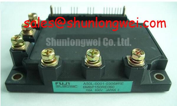
The confirmed product identity is a Fuji Electric IGBT module with a 600 V voltage rating and a 150 A current rating. These are Official Specifications, not a complete set of operating conditions. Gate-drive limits, switching characteristics, thermal limits, terminal assignments and mounting requirements should be checked against the applicable Fuji Electric documentation before the unit is energized.
| Product detail | Confirmed specification |
|---|---|
| Model | 6MBI150U2B-060 |
| Manufacturer | Fuji Electric |
| Rated voltage | 600 V (Official Specification) |
| Rated current | 150 A (Official Specification) |
| Package | Module (Official Specification) |
Preventing Spurious Faults: Gate Bias and Miller Clamp Checks for 6MBI150U2B-060
A trip that appears only during switching calls for measurements at the module terminals, not an immediate change to the protection threshold. As a Design Consideration, rapid voltage transitions can couple into a gate circuit and disturb the intended off state. With appropriate isolated probes and a controlled test procedure, compare the gate-to-emitter waveform, driver command and collector switching waveform. Look for a gate excursion that coincides with the opposite switching event, while also checking driver supply behavior and the integrity of the gate return.
Negative gate bias and an active Miller clamp are circuit-level techniques, not confirmed features or required settings of this model. If the existing driver uses either technique, verify its operation against the driver schematic and the module’s documented gate limits. Keep the gate-drive loop compact to reduce unwanted coupling, then establish any gate resistance, bias and timing settings through system-level switching tests. A gate waveform that looks acceptable at the driver board may differ at the module terminals because of wiring impedance.
For an industrial inverter welder or a medium-frequency induction-heating supply, suitability depends on the actual switching circuit and operating conditions; the equipment name alone establishes no compatibility. Fuji Electric’s high-speed discrete IGBT information provides useful context on device categories, but discrete-device characteristics should not be transferred to this module. Likewise, the company’s IGBT module range is a reference for module technologies, not a substitute for the specification of 6MBI150U2B-060.
6MBI150U2B-060 Circuit Protection: Terminal Verification and Voltage Margin
Before connecting busbars, trace each power and control connection from the equipment drawing to the marked module terminals and the applicable pinout. Check that insulating barriers and conductor spacing remain as intended after assembly. As a Design Consideration, creepage and clearance must be assessed in the completed equipment, where contamination, enclosure conditions and the applied voltage determine the required distances. The module’s 600 V rating alone cannot establish an acceptable equipment spacing.
Inspect busbar seating, support and fastening in equipment exposed to vibration. A connection that shifts under mechanical stress can complicate both temperature measurements and fault diagnosis. Verify the specified fastening method for the actual terminal hardware rather than applying a torque value inferred from another module. When investigating an intermittent shutdown, inspect connection surfaces and compare voltage measurements across suspect joints under an approved test procedure; a shutdown by itself does not identify the joint as the cause.
The 6MBI300U-120 is a separate model for a specification comparison, not an assumed drop-in alternative. Its voltage and current ratings, terminal arrangement, package fit and driver requirements all need independent verification. The 2MBI150UC-120 may also be considered when reviewing other positions in a power-conversion schematic, but its circuit role must be established from that schematic; its model designation does not make it a verified rectifier companion to this unit.
Atmospheric radiation, altitude and single-event burnout are reliability topics that cannot be reduced to a failure-in-time figure from the confirmed ratings on this page. For an installation with unusual exposure conditions, engineers should obtain application-specific manufacturer guidance and assess voltage margin under measured operating and transient conditions. The Power Electronics Masterclass offers broader system-reliability context; it does not establish a lifetime or failure rate for 6MBI150U2B-060.
6MBI150U2B-060 Thermal Interface: Grease Coverage and Mounting Checks
Clean and inspect the mating surfaces before mounting the module. Look for debris, damage or old interface material that could prevent even contact. Apply the thermal interface material using the method specified for the assembly, avoiding visible gaps and excess material at the edges. A universal grease thickness cannot be assigned to this module from the confirmed product data; the interface material, heatsink finish and mounting instructions determine the appropriate process.
Seat the module evenly and tighten its fasteners in the sequence specified for the assembly. Do not use the screws to force a damaged or poorly supported surface into position. During maintenance, compare temperatures at repeatable locations under comparable load and cooling conditions, and inspect the heatsink airflow path for accumulated dust. A rising temperature may reflect an interface, airflow or electrical-load issue, so investigate those conditions before attributing it to the module.
Maintenance note: Isolate the equipment before clearing the heatsink or rechecking fasteners, and confirm the specified tightening procedure before returning it to service.
Moisture and condensation also deserve attention during a cold start or after an enclosure has been opened. As a Design Consideration, verify that the equipment’s environmental controls and inspection procedure keep conductive moisture away from power terminals and control connections. Neither a wide operating-temperature range nor a condensation tolerance has been established here as an official specification for this model.
6MBI150U2B-060 Thermal-Electrical Checks During DC-Bus Surges
When a DC-bus overvoltage fault occurs during motor deceleration, capture the bus waveform and correlate it with the drive command and braking-circuit status. As a Design Consideration, regenerative energy can raise bus voltage if the system cannot absorb it quickly enough. The relevant check for this 600 V module is whether the voltage across its switching terminals, including transient overshoot, stays within the applicable documented limits during the tested event.
Do not assume that 6MBI150U2B-060 contains a braking switch or that its 150 A rating sizes an external braking resistor. If the equipment uses a separate braking circuit, its switch, resistor and control behavior must be assessed from the equipment schematic and measured duty conditions. Inspect the DC-link connections and switching waveforms as well: an apparent regeneration fault can coexist with a connection or switching-transient problem, and the fault log alone may not distinguish them.
For a prospective replacement, compare the existing circuit’s terminal map, driver interface, cooling assembly and measured bus behavior with the module’s applicable documentation before commissioning. Complete that check under the equipment manufacturer’s service procedure, with protection functions active and voltage observations made at the points that determine stress on the module.