


Content last revised on April 16, 2026
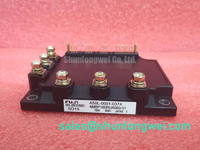
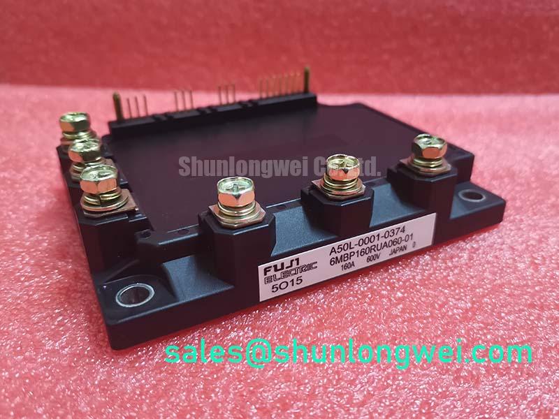
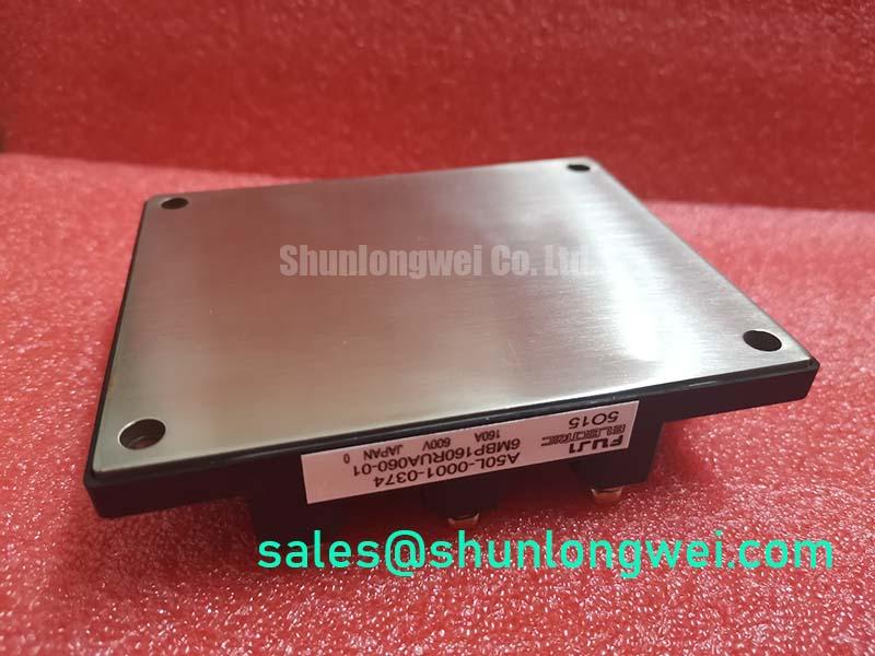
Fuji Electric 6MBP160RUA060-01: An In-Depth Analysis of the 600V/160A 7-in-1 PIM IGBT Module
Introduction to a System-on-Chip Power Solution
The Fuji Electric 6MBP160RUA060-01 is a highly integrated 7-in-1 Power Integrated Module (PIM) designed to streamline the development of compact and efficient motor drives and power conversion systems. This module provides a robust power core with specifications of 600V | 160A | VCE(sat) 2.7V (max), engineered for high reliability. Key benefits include significant component count reduction and simplified thermal management pathways. For engineers tasked with accelerating time-to-market for variable frequency drives, this module answers the challenge by consolidating a three-phase converter, a three-phase inverter, and a brake chopper into a single, pre-validated component. For motor drive applications up to ~40kW requiring a consolidated power stage, the 6MBP160RUA060-01 offers an optimal balance of integration and performance.
Key Parameter Overview
Decoding the Specs for System Integration
The electrical and thermal characteristics of the 6MBP160RUA060-01 are pivotal for achieving a reliable and efficient system design. The parameters listed below serve as the foundation for accurate performance simulation, thermal hardware selection, and defining operational safety margins.
| Parameter | Symbol | Condition | Value | Unit |
|---|---|---|---|---|
| Inverter Part | ||||
| Collector-Emitter Voltage | VCES | - | 600 | V |
| Collector Current (DC) | IC | - | 160 | A |
| Collector-Emitter Saturation Voltage | VCE(sat) | IC = 160A | 2.7 | V |
| FWD Forward Voltage | VF | IC = 160A | 2.5 | V |
| Converter Part | ||||
| Repetitive Peak Reverse Voltage | VRRM | - | 600 | V |
| Average Forward Current | IF(AV) | - | 160 | A |
| Brake Part | ||||
| Collector-Emitter Voltage | VCES | - | 600 | V |
| Collector Current (DC) | IC | - | 80 | A |
| Thermal Characteristics | ||||
| Operating Junction Temperature | Tj | - | +150 | °C |
| Short Circuit Withstand Time | tsc | VCC=400V, Tj=125°C | 10 | µs |
Download the 6MBP160RUA060-01 datasheet for detailed specifications and performance curves.
Application Scenarios & Value
System-Level Benefits in Industrial Motion Control
The primary value of the 6MBP160RUA060-01 lies in its ability to drastically simplify the design of low-to-mid-power AC motor drives. Consider the engineering challenge of designing a compact Variable Frequency Drive (VFD) for a conveyor system. A traditional design would require selecting, sourcing, and mounting separate rectifier diodes, six inverter IGBTs with their anti-parallel diodes, and a brake chopper transistor. This multi-component approach increases PCB complexity, assembly time, and the number of thermal interfaces, creating multiple potential points of failure. The 6MBP160RUA060-01 consolidates these functions into one package. This integration provides a single, optimized thermal path to the heatsink, simplifying thermal management. Its 10µs short-circuit withstand time is a critical parameter that provides the necessary robustness to survive common industrial faults like motor phase-to-phase shorts, enhancing the overall reliability of the drive system.
For systems that require a different power level but benefit from a similar integrated architecture, models such as the 6MBP100RA060 and the 6MBP200RA060 offer lower and higher current ratings, respectively, within a comparable module family.
Technical Deep Dive
A Closer Look at the 7-in-1 Architecture
The "7-in-1" designation refers to the seven primary semiconductor switches and diodes integrated within the module: a three-phase diode bridge rectifier (converter), a three-phase IGBT bridge (inverter), and a single IGBT with an anti-parallel diode for the dynamic brake chopper circuit. This architecture is often called a CIB module (Converter-Inverter-Brake). The significance of this integration extends beyond mere component reduction. By co-packaging these elements, Fuji Electric minimizes the internal stray inductance between the components. This is crucial for reducing voltage overshoots during high-speed switching events, which in turn reduces stress on the IGBTs and can lower the system's overall electromagnetic interference (EMI) signature. The integrated NTC thermistor acts as a built-in sensor, providing a direct and accurate reading of the module's internal temperature. This is analogous to having a thermometer placed directly on an engine block rather than on the car's dashboard; it offers a far more immediate and relevant data point for implementing effective over-temperature protection, preventing catastrophic failure and extending the service life of the drive.
Frequently Asked Questions (FAQ)
What is the primary benefit of the 7-in-1 PIM configuration?
The primary benefit is system simplification. It combines the converter, inverter, and brake circuits into a single component, reducing the bill of materials (BOM), minimizing PCB complexity, simplifying the thermal design with a single mounting surface, and accelerating the assembly process for motor drives.
How does the VCE(sat) of 2.7V impact system efficiency?
The Collector-Emitter Saturation Voltage, VCE(sat), represents the voltage drop across the IGBT when it's fully on. This voltage drop, multiplied by the current flowing through it (IC), determines the conduction power loss. A lower VCE(sat) means less energy is wasted as heat during operation, which directly improves the overall energy efficiency of the motor drive and reduces the cooling requirements for the heatsink.
What is the role of the integrated NTC thermistor?
The integrated Negative Temperature Coefficient (NTC) thermistor provides a real-time analog signal that corresponds to the module's baseplate temperature. This allows the drive's control system to constantly monitor the thermal state of the power stage and trigger protective measures, such as reducing the output current or initiating a shutdown, if the temperature exceeds safe operating limits.
Is the 6MBP160RUA060-01 suitable for regenerative applications?
Yes, the inclusion of an integrated brake chopper circuit makes it inherently suitable for applications involving regenerative energy. When a motor decelerates, it acts as a generator, sending power back to the drive. The brake chopper is used to dissipate this energy into a braking resistor, preventing the DC bus voltage from rising to dangerous levels.
What does the 10µs short-circuit withstand time signify for design reliability?
This specification guarantees the IGBTs within the inverter can survive a direct short-circuit event at the output terminals for at least 10 microseconds. This brief window is critical, as it provides enough time for the drive's protection circuitry to detect the fault and safely shut down the gate signals before the IGBTs are permanently damaged, significantly enhancing the robustness of the drive in harsh industrial environments.
Strategic Considerations for Power System Design
Accelerating Time-to-Market with Integrated Solutions
In the fast-paced industrial automation market, the speed of development and deployment is a significant competitive advantage. Adopting an integrated power module like the 6MBP160RUA060-01 shifts engineering focus from the component level to the system level. Instead of spending valuable time on the intricate details of power device layout, gate drive optimization, and component-level thermal analysis, design teams can leverage a pre-engineered, pre-validated power core from a trusted manufacturer like Fuji Electric. This approach de-risks the most failure-prone part of a power electronics system, allowing resources to be allocated to software development, user interface design, and other differentiating features that provide greater value to the end customer.