

Content last revised on September 23, 2026
6MBI50FA-060-01 Thermal-Electrical Optimization: Transient Thermal Impedance Practical Tuning
Start incoming inspection by isolating the 6MBI50FA-060-01 from the drive, confirming the terminal markings against the original equipment documentation, and recording cold-state resistance or diode-test readings before applying any gate signal. Do not assign a terminal polarity from physical position alone when the equipment drawing is unavailable.
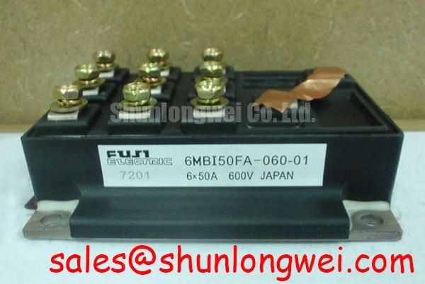
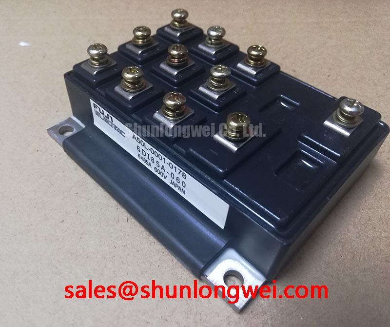
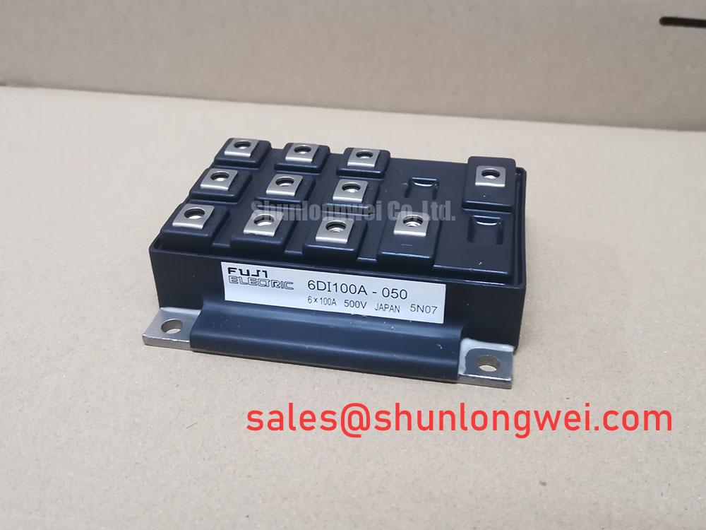
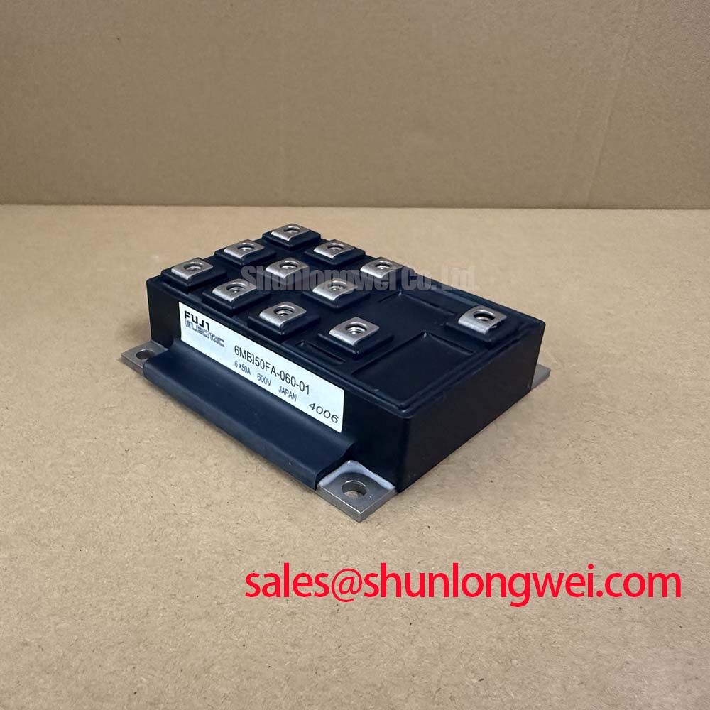
This Fuji Electric six-pack IGBT module is officially rated at 600 V collector-emitter voltage and 50 A continuous collector current at Tc = 80°C. Its published typical saturation voltage is 2.1 V VCE(sat). These values are official specification data for component evaluation; actual inverter current capability remains dependent on switching frequency, duty cycle, cooling, load profile, and the manufacturer’s electrical curves.
For pulsed overload assessment, designers should treat the case temperature and transient thermal impedance as separate variables. A short acceleration or regenerative event can produce a junction temperature rise before the heatsink responds. The correct engineering method is to use the manufacturer’s transient thermal impedance curves with the measured case temperature and the actual pulse sequence. A multi-RC thermal model can then estimate peak junction temperature, but the result remains an engineering calculation that requires validation during the real switching waveform.
Inspect the mounting surface for flatness, contamination, and uneven contact before thermal testing. The thermal interface material should be applied as a thin, continuous layer selected for the actual mounting surface and pressure system. Mounting force, heatsink geometry, airflow, and enclosure temperature should be verified by the system designer rather than inferred from the module name.
💡 Bench Tip: Keep the module ESD protected and compare cold-state diode readings with a known-good reference from the same circuit position before concluding that a power path is damaged.
6MBI50FA-060-01 Operational Boundaries: Evaluating Static and Dynamic Current Distribution
The six-pack configuration integrates the switching devices required for a three-phase bridge, which can simplify a VFD or servo inverter layout. The official isolation voltage is 2500 V AC for 1 minute, providing a defined dielectric test rating between the module terminals and its isolated baseplate or mounting surface. This rating should not be treated as a complete system safety certification; creepage, clearance, insulation materials, pollution degree, and production testing remain system responsibilities.
When modules or power paths are paralleled, static current distribution should be checked using the measured VCE(sat) behavior at the intended current and temperature. IGBT conduction characteristics commonly shift with temperature, and the direction and magnitude of current sharing must be confirmed from the relevant device curves rather than assumed from the nominal 2.1 V typical VCE(sat) value. Symmetrical busbar geometry and matched gate-loop impedance are important design considerations for reducing unequal turn-on and turn-off behavior.
During commissioning, measure phase-leg current with properly rated probes and compare the switching edges under the same DC-link and load conditions. Unequal current may involve gate-drive timing, emitter wiring, busbar resistance, stray inductance, sensor placement, or thermal imbalance. An oscilloscope comparison against a known-good phase is more reliable than assigning one measured waveform to a single internal fault.
This product is an IGBT module, not a thyristor. SCR parameters such as IGT and VGT do not define its gate-drive requirement. Gate voltage, gate resistance, pulse timing, protection thresholds, and negative-bias practices must be taken from the applicable Fuji Electric documentation and the original inverter design. The Fuji Electric V-Series IGBT Application Manual provides relevant application guidance, while the Variable-Frequency Drive inverter overview offers broader topology context.
6MBI50FA-060-01 Thermal-Electrical Optimization: DC-Bus Low-Inductance Laminated Busbar Practical Tuning
Turn-off overshoot is governed by the interaction between DC-link voltage, commutation current, switching speed, and the parasitic inductance of the complete power loop. In practical testing, the peak collector-emitter voltage can be viewed as the applied DC-link voltage plus the inductive voltage generated during current change. This relationship is an engineering calculation, not an additional rating for the module.
Keep the high-current commutation path compact and arrange the positive and negative conductors so their magnetic fields partially cancel. A laminated busbar is one possible approach, but its suitability depends on insulation construction, current distribution, mechanical clearances, and the position of the DC-link capacitor relative to the module terminals. The designer should verify the resulting peak voltage directly at the module terminals with a properly compensated differential probe.
Snubber selection should follow measured ringing frequency, energy, pulse repetition, and capacitor voltage stress. A capacitor value selected without waveform data can add circulating current or create a new resonance. Validate the complete network during the highest expected current and temperature conditions, then compare the observed peak against the 600 V VCES rating and the system’s required operating margin.
For a replacement evaluation, the larger-current 2MBI400TB-060-01 may appear in the same broad power-electronics discussion, but its electrical ratings, gate behavior, mechanical interface, thermal path, and protection settings must be independently checked. It should not be treated as a drop-in alternative without documented system validation.
For gate-loop routing, minimize shared inductance between the driver return and high-current commutation paths. The system engineer should verify gate-emitter voltage at the module pins, confirm that the driver remains within its specified range during switching, and inspect ringing before increasing switching speed. The Precision Gate Drive Design guide provides a useful reference for this evaluation.
Field Diagnostics & Commissioning: Sizing Braking Resistors and Chopper Transistors in 6MBI50FA-060-01 Topologies
In a servo actuator or BLDC motion system, deceleration can return kinetic energy to the DC link. If the control system cannot send that energy back to the source, a braking chopper and external resistor may be used. The 6MBI50FA-060-01 provides a six-pack bridge, but the complete braking arrangement must be confirmed from the original drive topology; the presence of the module does not prove that a braking transistor or resistor is internally assigned.
Resistor selection begins with the measured regenerative energy, DC-link voltage range, braking duration, repetition rate, and allowable resistor temperature. Instantaneous braking power and average thermal power are different design quantities. The resistor must tolerate the pulse energy as well as the repeated thermal load, while the chopper device must be evaluated for collector-emitter voltage, peak current, switching loss, and cooling conditions.
During commissioning, monitor DC-link voltage, chopper gate waveform, resistor current, and module case temperature during controlled deceleration. A missing gate pulse, unexpected voltage rise, or irregular current waveform may indicate a control-timing issue, sensing problem, wiring inductance, or thermal limitation. Compare each signal with the drive’s documented reference waveform before replacing the power module.
Before any cold test, isolate the DC link and wait for the manufacturer-specified discharge process. Check the braking resistor, chopper path, gate-drive supply, and protection feedback independently, then repeat the test at progressively higher regenerative demand within the equipment’s approved operating limits. Long-term thermal cycling, battery charging and discharging, or kinetic-energy absorption claims require application-specific validation; no field-life or failure-rate figure is established here.