




Content last revised on September 10, 2026
6DI100A-050 Incoming Inspection and Identification
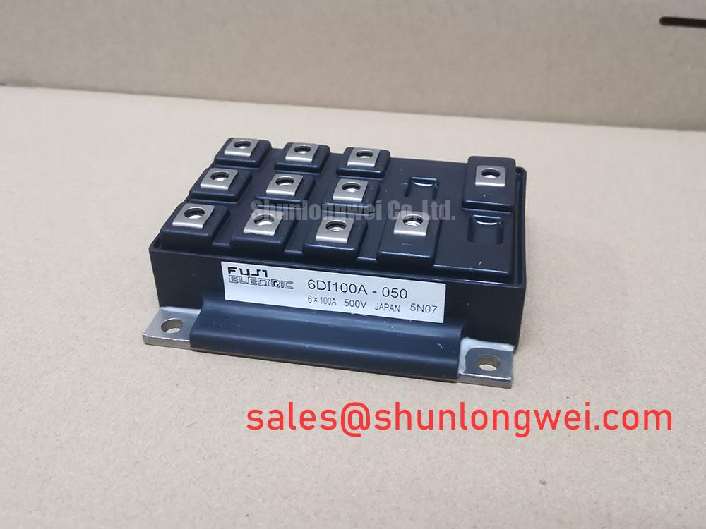
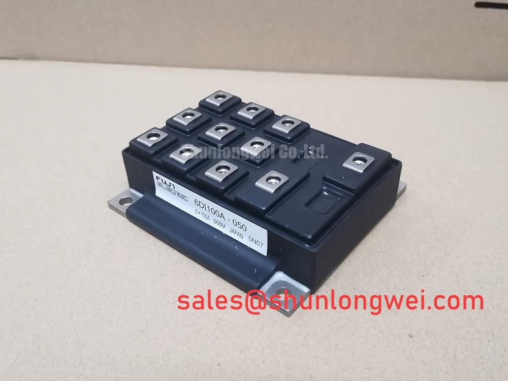
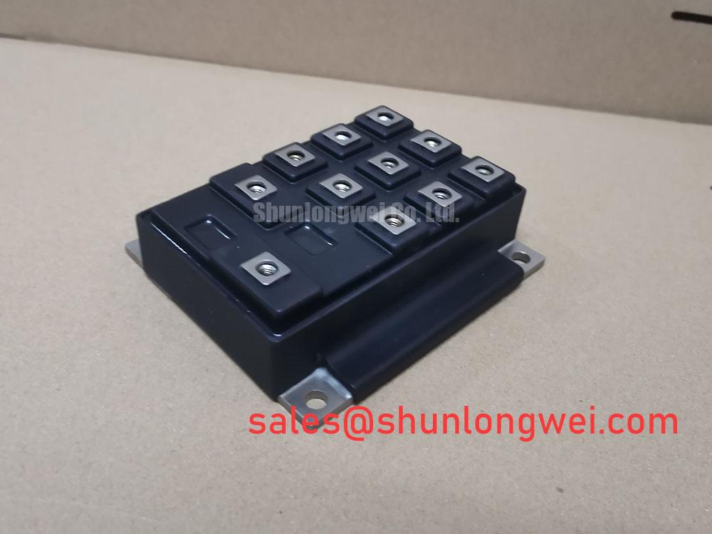
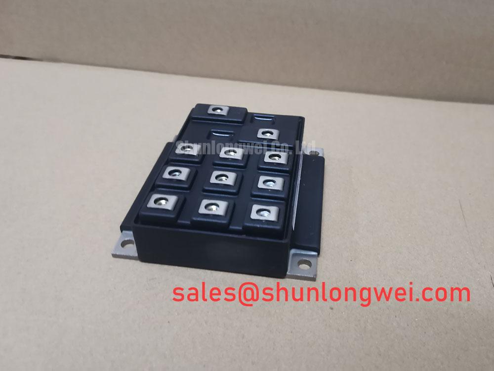
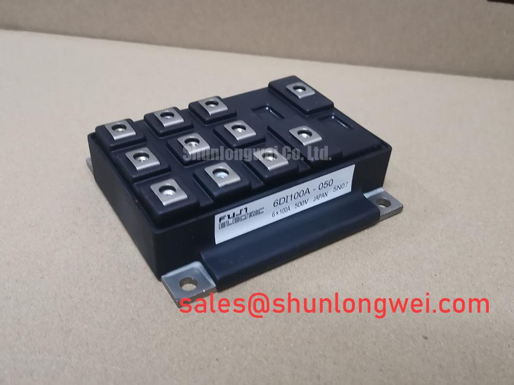
Begin incoming inspection by isolating the 6DI100A-050, recording its marking, checking the package for visible damage, and confirming that the intended circuit voltage and current remain within the published device ratings. Fuji Electric identifies this unit as a Power Transistor Module with an official rated voltage of 600.0 V and an official rated current of 100.0 A. These ratings establish the component identity and electrical boundary; they do not replace a system-level switching, thermal, or protection review.
| Manufacturer | Fuji Electric |
| Model | 6DI100A-050 |
| Package | Power Transistor Module |
| Rated voltage | 600.0 V, Official Specification |
| Rated current | 100.0 A, Official Specification |
For an incoming bench check, use the original equipment documentation to confirm terminal polarity and the permitted test method before applying a meter. A diode-range reading across a known power path can help compare the unit with a documented good reference, but a meter result alone cannot confirm switching performance, insulation integrity, gate condition, or short-circuit ruggedness. 💡 Bench Tip: protect the module from ESD and record cold-state readings beside the visual inspection record so later comparisons are made under the same conditions.
Transient Dynamics & Electrical Design: Baseplate Convexity Compensation and Screw on 6DI100A-050
Mounting quality directly affects the thermal path from the module base to the heatsink. Clean both mating surfaces, inspect for burrs or contamination, and apply a uniform thermal interface layer without relying on excessive compound to compensate for mechanical distortion. A controlled TIM thickness in the manufacturer or heatsink assembly specification should be treated as an Engineering Recommendation; the supplied product data does not establish a universal installation thickness for every heatsink.
When the baseplate and heatsink are not perfectly matched, tightening one corner first can create uneven contact pressure and leave localized thermal resistance. Use the mechanical drawing for hole position, fastener type, washer arrangement, and approved torque. Tighten in a diagonal sequence with progressive passes, then inspect for movement or visible extrusion of the interface material. Keep high-current busbars physically supported so their weight and vibration do not load the module terminals.
In a forklift traction inverter or other low-voltage material-handling drive, minimize the commutation loop area to limit stray inductance and switching overshoot. Designers should verify the measured collector-emitter peak against the DC-link voltage during switching tests. If the waveform shows ringing, compare probe grounding, busbar geometry, gate-loop routing, and clamping behavior before attributing the symptom to the module itself. The Fuji Electric power semiconductor resource provides useful manufacturer-level context for evaluation.
6DI100A-050 Circuit Protection & Reliability: Calibrating Thermal Cycling Margins of Internal Braking
The supplied product information confirms voltage, current, and package category, but it does not confirm an internal braking IGBT, braking resistor rating, short-circuit duration, or surge-current capability for this specific listing. A traction system designer should therefore verify the complete circuit topology before assigning regenerative energy to this module. During deceleration, the DC link, braking switch, resistor, battery interface, and control firmware must be assessed together because resistor energy absorption and semiconductor losses are system-dependent.
Desaturation protection may be considered where the gate-driver architecture supports it. Detection delay, blanking time, fault response, and soft turn-off behavior must be selected from the driver design and validated with a current-controlled short-circuit test. A two-stage turn-off approach can reduce voltage overshoot compared with an abrupt gate interruption, but its timing and gate resistance remain engineering variables rather than factory specifications for the 6DI100A-050.
For bidirectional DC-DC battery charging and discharge systems, log device-case temperature, DC-link behavior, braking duty, and recovery intervals during representative load cycles. If thermal rise accumulates, investigate switching loss, resistor sizing, airflow, sensor placement, and control limits together. The neutral reference 7MBR10KA060 may also be reviewed as an associated rectification-stage product, subject to circuit compatibility and documentation review.
6DI100A-050 Circuit Protection & Reliability: Calibrating Kelvin Emitter Connection
Do not assume a Kelvin emitter terminal or auxiliary emitter return unless it is explicitly shown in the verified terminal drawing for the purchased configuration. The main power return should be kept separate from the gate-driver signal return wherever the package and schematic permit. This reduces mutual coupling between high di/dt current and the gate reference, helping the engineer distinguish genuine gate-loop oscillation from measurement error.
Route the gate-drive return with its signal path, keep the power commutation path compact, and avoid sharing narrow copper with control-ground currents. During troubleshooting, use a short-reach differential probe or an appropriately rated isolated measurement method, then compare gate-emitter behavior at the module pins rather than at a remote driver connector. Check for false turn-on, excessive ringing, unequal phase behavior, and changes under different cable positions. Final clearance and creepage must follow the applicable system insulation design and working-voltage requirements.
6DI100A-050 Circuit Protection & Reliability: Evaluating Thermal Capacitance vs Heat Sink
Peak junction temperature during a pulsed overload cannot be established from the 100.0 A rating alone. Designers should obtain the applicable transient thermal impedance information for the exact device revision and combine it with measured conduction loss, switching loss, case temperature, pulse width, duty cycle, and heatsink response. A multi-RC thermal model can then estimate the junction temperature trajectory, but the result remains an Engineering Calculation that requires correlation against controlled thermal testing.
For a suspected overheating event, inspect the mounting footprint, TIM spread, heatsink flatness, fan or duct condition, current waveform, gate timing, and fault history. Compare cold-start and warmed-up electrical readings, while avoiding energized probing beyond the laboratory safety procedure. A similar-reference device such as 6MBP100TEA060-50 can support a neutral specification comparison, but substitution requires confirmation of terminal arrangement, dynamic ratings, protection behavior, and mechanical fit.
When the converter uses quasi-resonant or half-bridge behavior, switching-node waveform interpretation should be tied to the actual topology rather than a generic fault assumption. The application reference Resonant Topologies in Home Appliances offers a topology-level comparison that can help structure that review.