

Content last revised on September 19, 2026
6MBP75RA060-01 Circuit Protection & Reliability: Calibrating Junction-to-Case Thermal Network Simulation
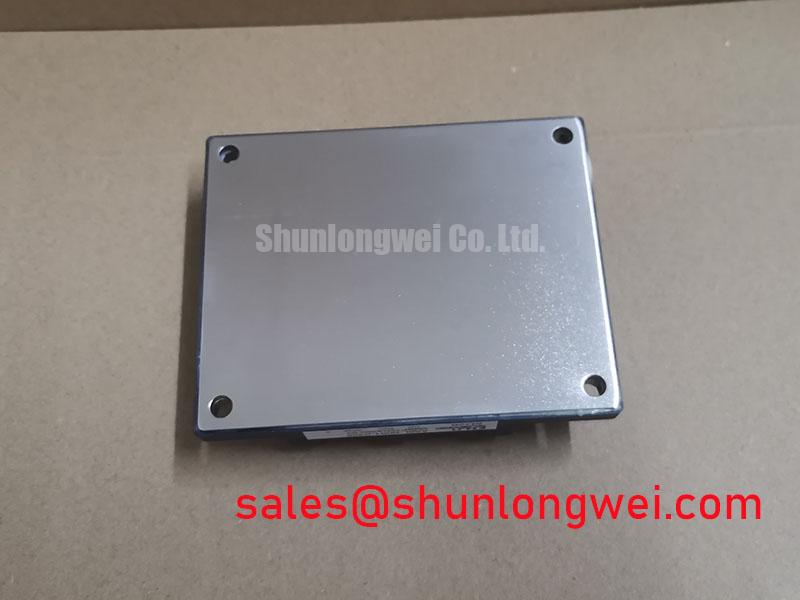
With the DC link discharged and isolated, first inspect the 6MBP75RA060-01 power terminals, mounting face, and connector area for looseness, corrosion, heat marking, or mechanical distortion before making any cold-state resistance comparison with the removed unit.
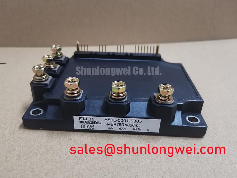
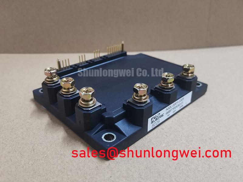
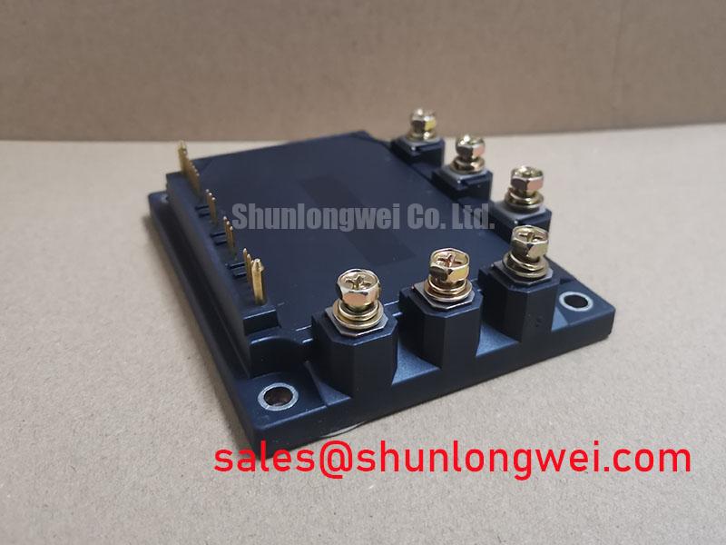
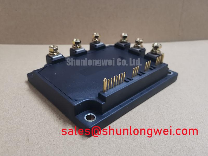
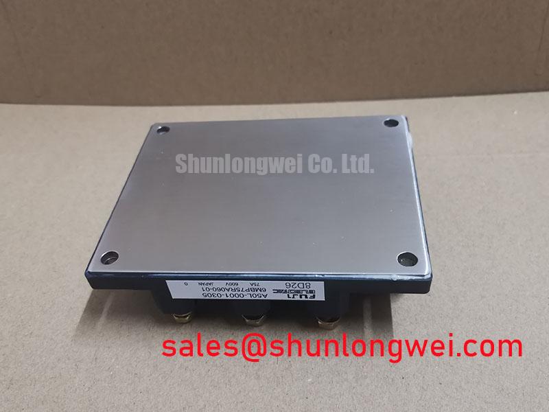
The Fuji Electric 6MBP75RA060-01 is an IPM module rated at 600.0 V and 75.0 A in a module package, based on the official product specification. For repair work, those ratings establish the electrical identity that must be matched against the original equipment documentation and the inverter’s actual DC bus conditions. Terminal functions, driver supply requirements, pin assignments, and protection timing must be verified from the original circuit documentation rather than inferred from the module designation.
| Official Specification | Value |
|---|---|
| Manufacturer | Fuji Electric |
| Part Number | 6MBP75RA060-01 |
| Product Category | IPM Module |
| Rated Voltage | 600.0 V |
| Rated Current | 75.0 A |
| Package | Module |
When an inverter trips after a short loaded run but passes a basic bench check, do not treat the cold measurement as proof of thermal health. Compare the power-stage mechanical condition, heatsink contact pattern, fan operation, airflow obstruction, and thermal-interface coverage before returning the equipment to service. The 600.0 V and 75.0 A ratings are specified electrical ratings, but they do not independently define the installed thermal path through the system heatsink, interface material, enclosure, and cooling arrangement.
A junction-to-case transient thermal model is an Engineering Calculation when its resistor-capacitor values are taken from the applicable manufacturer data. It is useful for estimating how a pulsed load can raise junction temperature before the case temperature visibly follows. The system engineer should use the approved transient thermal curves and measured load waveform to evaluate peak junction margin during overloads, start-up events, and repeated power cycling. Without the model-specific thermal impedance data, a numerical thermal prediction would not be reliable.
For field investigation, capture operating current, switching activity, heatsink temperature trend, and cooling response under the same conditions that caused the shutdown. Check whether the mounting surface is flat, clean, and free of embedded debris that can create a local contact gap. A thermal image can identify uneven heat distribution, but it should be correlated with electrical measurements because surface temperature alone does not establish semiconductor junction temperature.
⚠️ Field Alert: Isolate all stored energy before disconnecting module or gate-drive wiring, and apply thermal interface material as a thin, uniform layer in accordance with the equipment manufacturer’s mounting procedure.
Design Consideration: maintain clearance and creepage arrangements according to the complete inverter’s voltage class, contamination environment, and applicable safety standard. The module’s stated voltage rating must not be used as a substitute for verifying board spacing, busbar insulation, enclosure protection, or the system’s thermal shutdown strategy.
6MBP75RA060-01 Circuit Protection & Reliability: Calibrating High-Frequency Commutation Loop Inductance
Turn-off overshoot should be examined at the module terminals with a measurement method suitable for fast switching events. In practical terms, peak voltage can rise above the DC-link voltage as stray commutation inductance interacts with the rate of current change. This relationship guides the investigation: reducing loop inductance helps suppress inductive overshoot, while the final peak margin must be verified against the actual DC-link voltage during switching tests.
Design Consideration: keep the commutation path between the DC-link capacitors and power module compact, mechanically secure, and geometrically symmetrical where the inverter topology requires matching current paths. Inspect laminated busbars, capacitor hardware, terminal joints, and conductor routing after any field repair. A loose fastener, changed cable route, or degraded capacitor connection can alter the switching waveform even when the replacement module itself is correctly installed.
Snubber and clamp networks are system-level circuits, not inherent specifications of the 6MBP75RA060-01. Their component values, dissipation capability, and placement should be determined from measured ringing frequency, peak voltage, pulse energy, and the existing inverter design. Avoid transferring snubber values from a different cabinet or converter rating without validating the waveform at the repaired equipment.
In commercial string inverter and micro-grid energy-storage evaluations, switching frequency, load profile, ambient temperature, and airflow all affect losses and thermal response. Engineers should confirm the original drive strategy and cooling capability before changing operating conditions. Fuji Electric’s power semiconductor and IPM module information provides useful manufacturer context for power-module families, while model-specific limits remain subject to the applicable documentation.
Where a repair bill of materials requires a related power-stage reference, the 6MBI15L-060 can be reviewed as a separate system-topology component. Its use, terminal arrangement, electrical ratings, and driver compatibility require independent verification; it is not an automatic replacement for this IPM module.
Field Diagnostics & Commissioning: Environmental and Voltage-Stress Considerations for 6MBP75RA060-01 Topologies
Do not assign a cosmic-ray, neutron-flux, altitude, or single-event burnout failure rate to the 6MBP75RA060-01 without a manufacturer qualification document or a cited test report covering this exact device and operating condition. Such reliability figures depend on device construction, blocking voltage, temperature, mission profile, geographic location, and system voltage stress. No verified FIT value or service-life figure is stated here.
For a site located at elevated altitude, the immediate repair priority is more practical: verify the actual DC-link voltage, switching overshoot, cooling performance, contamination level, and insulation condition under the customer’s normal operating sequence. Design Consideration: the complete equipment designer should assess altitude-related insulation coordination and environmental derating using the governing system standard, not a generic assumption about the power module.
Commissioning should begin with a controlled no-load check, followed by monitored loading only after the gate-drive commands, fault indications, DC-link behavior, and cooling system respond as expected. If an intermittent fault appears only during high irradiance, battery charge transition, or grid reconnection, record the waveform and protection status rather than attributing the event to one cause. The result may indicate a supply disturbance, gate-drive issue, current-sensing error, thermal condition, or commutation-path problem that needs measurement against a known-good signal path.
For topology-level reading on resonant and half-bridge switching concepts that can influence stress analysis in appliance power stages, see Resonant Topologies in Home Appliances. That technical discussion is background material and does not establish operating limits for this specific Fuji Electric module.
6MBP75RA060-01 Circuit Protection & Reliability: Calibrating Fault-Clearing Dynamics: Type-I/II Desaturation
A replacement module should never be commissioned until the existing driver’s fault-clearing path has been checked as a complete chain. Verify the driver supply rails, control-command isolation, fault output, desaturation sensing route where present, and the shutdown response captured at the intended test points. The module part number alone does not confirm the driver’s short-circuit capability, desaturation threshold, or soft turn-off behavior.
Type-I and Type-II desaturation terminology can describe different driver or protection architectures, so field personnel should follow the equipment manufacturer’s schematic and service procedure. Where the inverter uses staged gate removal, its purpose is generally to limit stress during fault interruption by controlling the current transition and associated inductive voltage rise. The required timing, gate network, clamp strategy, and permissible short-circuit exposure are system-determined and must be validated with the approved driver and protection documentation.
Before applying full DC-link voltage, inspect the protection wiring for damaged connectors, incorrect polarity, and unintended shared return paths. Confirm that the measured fault signal reaches the controller and that the controller does not repeatedly re-enable the gate command into an unresolved power-stage fault. A single controlled fault-response verification, performed within the equipment’s approved test method, is more informative than repeated uncontrolled power-up attempts.
When the original repair record calls for comparison with another Fuji Electric power-module reference, the 6MBI100L-060 may be evaluated as a separate component. Engineers should compare its official ratings, physical mounting arrangement, terminal layout, control interface, and protection requirements with the original assembly before considering any redesign or service substitution. Fuji Electric’s PIM 7-Pack product information also illustrates why family-level module descriptions cannot replace model-specific integration checks.