Content last revised on September 17, 2026
Preventing Spurious Faults: Galvanic Gate Drive Isolation, Reinforced Guidelines for 6MBP75VBA060-50
Before connecting power, compare the equipment terminal map with the original assembly documentation, then perform cold-state diode-mode checks between the accessible power terminals to identify a consistent conduction path without applying gate-drive power. The 6MBP75VBA060-50 is a Fuji Electric intelligent power module rated at 600 V VCES and 75 A IC under its official maximum-rating conditions. Its specified collector-emitter saturation voltage is 2.2 V typical and 2.7 V maximum, while the integrated control supply operates from 13.5 V to 16.5 V. These parameters should be matched to the original inverter control board, DC-link level, cooling arrangement, and protection logic before a replacement is energized.
| Parameter | Official Specification | Integration Relevance |
|---|---|---|
| Collector-emitter voltage | 600 V | Suitable for equipment based on 200 V to 240 V AC line environments. |
| Collector current | 75 A | Defines continuous current capability under specified thermal conditions. |
| Collector-emitter saturation voltage | 2.2 V typical, 2.7 V maximum | Relevant to conduction-loss assessment and comparison during static checks. |
| Control supply voltage | 13.5 V to 16.5 V | Required operating range for internal logic and driver circuitry. |
| Over-temperature protection level | 150°C typical | Documented module protection characteristic; confirm its test conditions in the applicable documentation. |
| Short-circuit protection condition | 400 V specified condition | Use the documented DC-link and short-circuit test conditions when evaluating protection operation. |
For an incoming module check, confirm that the driver-board isolation scheme, auxiliary supply reference, control connector orientation, and power-terminal arrangement agree with the machine documentation. The module’s 13.5 V to 16.5 V control-supply requirement is an Official Specification; a controller supply outside that range should not be treated as a valid test condition. A gate command that appears correct at the controller may still become distorted at the module connection if the isolated drive return path shares a noisy power-current path.
💡 Bench Tip: Keep the module and control board on an ESD-safe bench, record cold-state diode-mode readings before installation, and compare questionable results with the removed assembly only after confirming identical terminal references.
Galvanic separation and common-mode transient tolerance are system-level Design Considerations, not published product guarantees for this module. Engineers should review isolation-barrier ratings, creepage, clearance, and driver behavior against the actual DC-link transient environment. Long control wiring, a floating driver reference, or an improperly routed gate-return conductor can contribute to false protection events or unintended switching signals. Probe gate-emitter behavior and the protection output at the module-side connection using a measurement arrangement suitable for the circuit’s voltage domain.
The Fuji Electric V-Series IGBT Application Manual provides useful background on practical gate-drive behavior, switching transients, and protection coordination. Where a gate-drive architecture uses an off-state bias approach, the system engineer can also review Evolution of Negative Off-Bias Gate Drive Circuits as a technical reference, then validate the chosen arrangement on the finished inverter rather than assuming a universal drive setting.
Benchtop Waveform Tuning: Mitigating Stress via Baseplate Contact and Screw Mounting on 6MBP75VBA060-50
Inspect the mating heatsink surface and module mounting area before fitting the 6MBP75VBA060-50. Remove old thermal compound completely, check for raised burrs or local damage, and use a thin, continuous thermal-interface layer in accordance with the cooling-system procedure. Thermal-interface thickness, clamping sequence, and mounting torque are Design Considerations because the applicable values depend on the module drawing, screw hardware, heatsink construction, and the equipment manufacturer’s service instructions.
A sequential tightening pattern helps distribute clamping force across the module base and can reduce the risk that a warped mating surface leaves localized poor thermal contact. After commissioning, uneven thermal patterns on the heatsink or unusual changes in temperature feedback warrant a renewed inspection of mounting contact, cooling flow, and sensor connections rather than an immediate assumption of a module fault.
Switching overshoot is heavily influenced by the complete commutation loop, including DC-link busbars, cable routing, and film-capacitor placement. As an Engineering Recommendation, minimize parasitic loop inductance to suppress turn-off voltage overshoot, then verify the resulting peak voltage against the DC-link condition using appropriate high-voltage waveform measurements. The soft or abrupt recovery behavior of the associated freewheel-diode path can influence ringing and radiated noise, so waveform assessment should include both the switching transition and recovery interval.
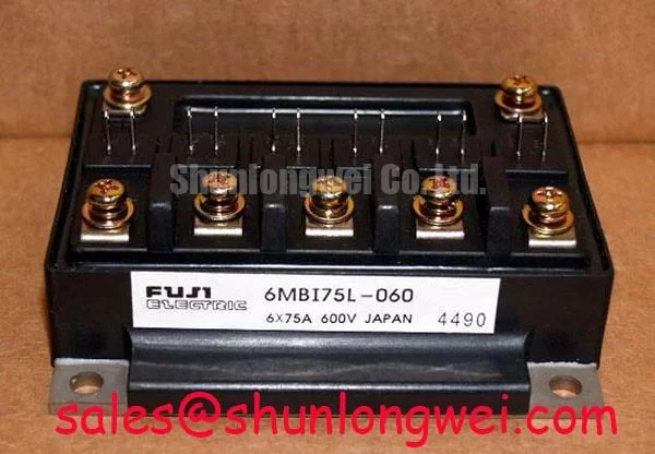
In systems with a separate front-end conversion stage, engineers sometimes examine a device such as the 6MBI15L-060 in relation to complementary rectifier or auxiliary power-stage requirements. That reference does not establish electrical interchangeability; terminal allocation, driver interface, protection functions, thermal design, and original equipment documentation remain the deciding checks.
6MBP75VBA060-50 Thermal-Electrical Optimization: Dynamic Power Loss Dissipation and Multi-R Practical Tuning
The stated 2.2 V typical and 2.7 V maximum VCE(sat) values are Official Specifications that help frame conduction-loss evaluation, but they do not substitute for testing the installed equipment at its real load current, switching frequency, cooling condition, and modulation method. The 150°C typical over-temperature protection level is a protection characteristic, not a preferred steady operating temperature.
For pulsed overload assessment, a system designer should use the applicable transient thermal-impedance data and a multi-resistance thermal model from the relevant product documentation. In practical terms, the calculation combines instantaneous device loss with the time-dependent junction-to-case thermal response and then checks the resulting estimated junction temperature against the operating boundary. This is an Engineering Calculation only when supported by documented thermal curves, measured case temperature, pulse duration, duty cycle, and power-loss assumptions.
During bench tuning, distinguish between thermal stress and switching stress. A higher measured case temperature can point toward insufficient heat transfer or cooling-system degradation, while excessive voltage ringing can remain present even with a cool baseplate. Capture current, DC-link voltage, module-side switching voltage, and available temperature feedback together. This avoids drawing a single-cause conclusion from one waveform or one temperature reading.
Commercial string inverters and micro-grid energy-storage converters are potential evaluation environments for this 600 V, 75 A IPM when their original electrical boundaries align. Any use in those systems requires verification of the original topology, protection timing, control-supply capability, fault reset behavior, and cooling capacity.
Field Diagnostics & Commissioning: Derating Guidelines and Mismatched Parameters in 6MBP75VBA060-50 Topologies
Commission the repaired assembly first with the machine’s prescribed safe startup process and verify the control supply remains within the official 13.5 V to 16.5 V range at the module interface. Confirm that the DC-link condition, including relevant transients, remains within the system’s design margin for the module’s 600 V blocking-voltage rating, and that the protection arrangement respects the documented 400 V short-circuit test condition. A mismatch between these system conditions and the original design can alter protection behavior even when the module passes basic static tests.
For parallel or symmetry-sensitive power paths, the positive temperature tendency of IGBT saturation voltage can support steady-state current-sharing behavior, but it does not guarantee dynamic current balance. Gate-loop length, return-path geometry, connector contact resistance, busbar symmetry, and cooling uniformity can all affect switching distribution. Engineers should inspect these factors and compare phase waveforms under controlled loading before deciding whether an imbalance is attributable to the module, the driver board, or the mechanical assembly.
If a hardware assessment requires comparison with another Fuji Electric unit, the 6MBI100L-060 can be reviewed as a separate technical reference. It should not be treated as an automatic replacement for 6MBP75VBA060-50; package interface, internal functions, pin arrangement, ratings, and protection implementation must be verified against the original equipment requirements.