Content last revised on September 10, 2026
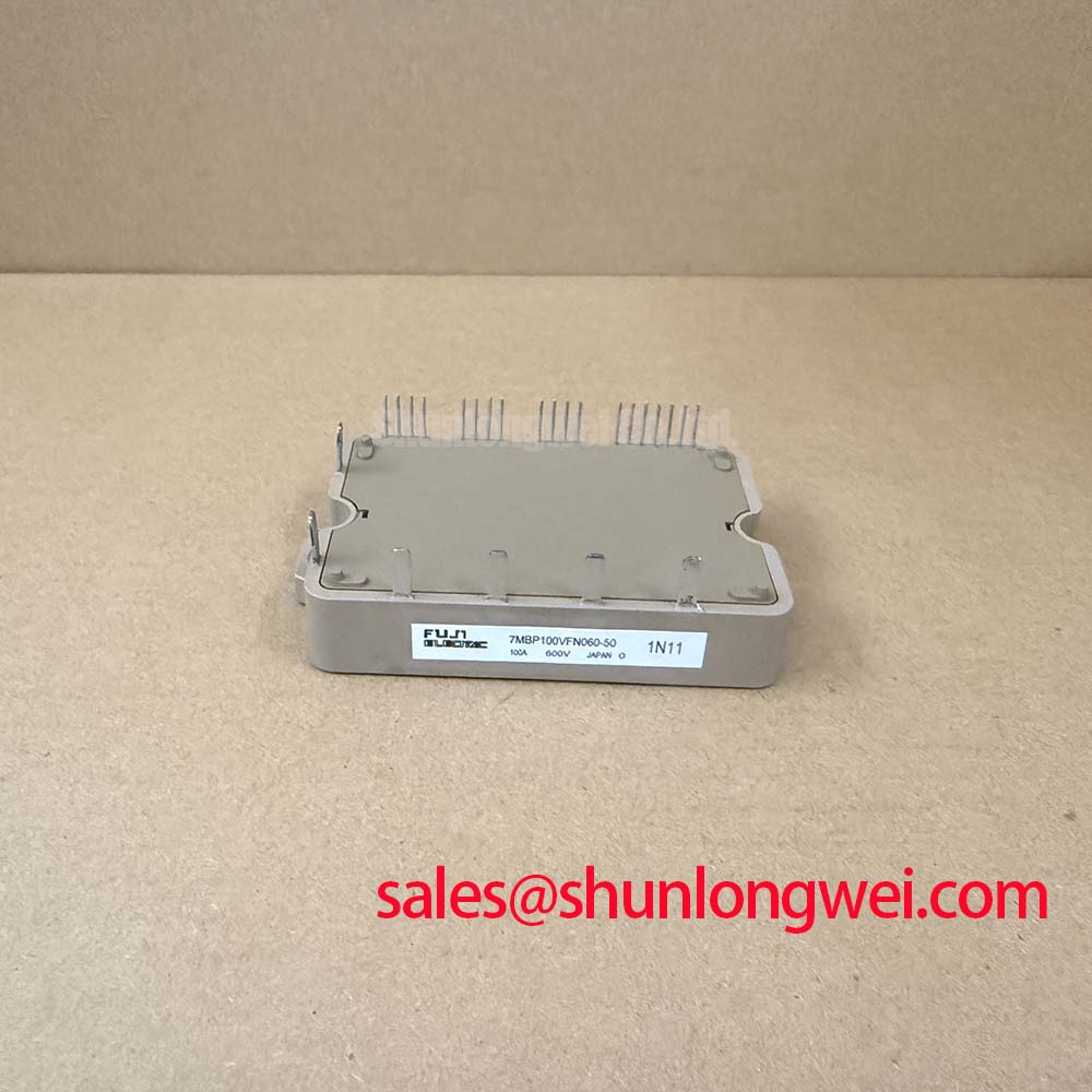
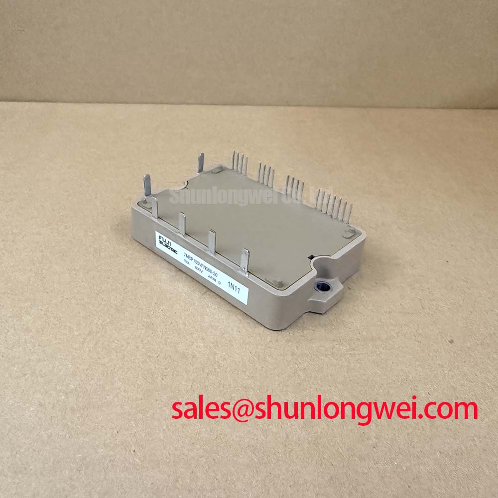
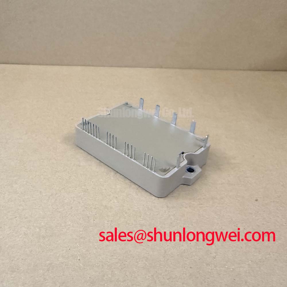
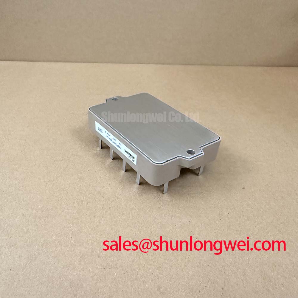
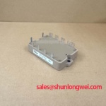
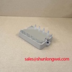
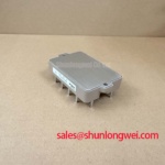
7MBP100VFN060-50 Fuji Electric IPM: Technical Specifications and Engineering Value
The Fuji Electric 7MBP100VFN060-50 integrates a drive circuit and multi-layered protection to simplify inverter designs and maximize power density. This intelligent power module delivers a robust combination of 600V | 100A | Rth(j-c)Q 0.31°C/W. The integration reduces overall component count and enables direct junction temperature sensing. Integrating the gate driver and protection functions within the module minimizes parasitic inductance. It eliminates external desaturation detection circuits, preventing drive failure during overcurrent events. For 400V class motor drive designs requiring integrated overheating protection, this 600V, 100A IPM is the optimal choice.
Key Parameter Overview
Decoding the Specs for Enhanced Thermal Reliability
| Parameter Group | Specification / Conditions | Rating / Value |
|---|---|---|
| Main Circuit (Inverter) | Collector-Emitter Voltage (Vces) | 600V |
| DC Collector Current (Ic) | 100A | |
| Peak Collector Current (Icp, 1ms) | 200A | |
| Collector Power Dissipation (Pc, 1 Device) | 403W | |
| Vce(sat) (Chip Typ, Tj = 25°C) | 1.25V | |
| Vce(sat) (Terminal Max, Ic = 100A) | 1.95V | |
| Forward Voltage (Vf Terminal Max, If = 100A) | 2.2V | |
| Main Circuit (Brake) | DC Collector Current (Ic) | 50A |
| Peak Collector Current (Icp, 1ms) | 100A | |
| Diode Forward Current (If) | 50A | |
| Vce(sat) (Terminal Max, Ic = 50A) | 1.85V | |
| Collector Power Dissipation (Pc, 1 Device) | 290W | |
| Control & Protection | Pre-Driver Supply Voltage (Vcc) | 13.5V to 16.5V (Recommended) |
| Overcurrent Protection Level (Ioc, Inverter) | Min 150A (Tj = 125°C) | |
| Short Circuit Protection Delay (tSC) | Typ 2 µs, Max 3 µs | |
| Overheating Protection Level (TjOH) | Min 150°C | |
| Under-Voltage Lockout Level (VUV) | 11.0V to 12.5V | |
| Thermal & Mechanical | Rth(j-c)Q (Inverter IGBT, Max) | 0.31°C/W |
| Rth(j-c)D (Inverter FWD, Max) | 0.55°C/W | |
| Rth(c-f) (Case to Fin, Typ) | 0.05°C/W | |
| Isolating Voltage (Viso, 1 min) | AC 2500 Vrms | |
| Mounting Screw Torque (M4) | 1.3 to 1.7 Nm | |
| Weight (Typ) | 190g |
Download the 7MBP100VFN060-50 datasheet for detailed specifications and performance curves.
Application Scenarios & Value
Achieving System-Level Benefits in High-Frequency Power Conversion
Engineers designing industrial conveyor system drives often face high starting torque demands that cause transient overcurrent conditions. The 7MBP100VFN060-50 manages these demands with a peak inverter current of 200A (1 ms) and integrated overcurrent protection active at 150A. This eliminates the risk of latch-up during sudden load changes in a variable frequency drive (VFD).
In automated production lines governed by electromagnetic compatibility standards such as IEC 61800-3, minimizing electrical noise is paramount. The module's soft-switching performance minimizes electromagnetic interference (EMI), protecting neighboring control electronics and reducing the reliance on large external input filters. This is particularly valuable in space-constrained industrial enclosures housing delicate programmable logic controllers (PLCs) or an industrial HMI.
While this module is ideal for 400V bus systems, for systems requiring higher voltage handling, the related 7MBP100VEA120-50 offers a Vces of 1200V.
Technical & Design Deep Dive
Integrated Protection Architecture for Harsh Operating Conditions
Traditional modules estimate chip temperature from the case. This is analogous to predicting engine temperature by touching the hood. Conversely, the 7MBP100VFN060-50 uses internal sensors to monitor the junction directly. It initiates a shutdown within microseconds if temperatures exceed 150°C. This localized sensing prevents thermal runaway during cooling system degradations.
The junction-to-case thermal resistance (Rth(j-c)Q) of 0.31°C/W acts as a highly efficient thermal pathway. This is analogous to a wide pipe allowing rapid heat dissipation to prevent localized hot spots and thermal runaway. Direct sensing enables tighter operating margins without risking safe operating area (SOA) violations.
Understanding the operational differences between integrated modules and discrete designs is crucial; engineers can refer to the guide on IPM vs discrete IGBTs to weigh system cost against design flexibility. For a deeper evaluation of gate control strategies and thermal runaway mechanisms, the engineer's guide to IGBT modules provides systemic details. Evaluating the Safe Operating Area is essential when operating near the absolute boundaries.
Proper fault diagnosis is key for system longevity. Review the procedures for IGBT failure analysis to identify root causes of field failures. This module utilizes the Fuji Electric V-Series IGBT chip technology to deliver low power loss.
What is the primary benefit of its integrated temperature protection? Direct junction sensing prevents thermal runaway.
What is the nominal isolating voltage? AC 2500 Vrms for one minute.
Frequently Asked Questions
Addressing Critical Engineering Design Queries
How does the junction-to-case thermal resistance (Rth(j-c)Q) of 0.31°C/W affect heatsink selection?
A lower Rth(j-c)Q of 0.31°C/W allows a higher power dissipation for a given case temperature. This directly reduces the size and volume of the required heatsink or active cooling system, enabling higher overall system power density.
What is the typical response of the 7MBP100VFN060-50 during an overcurrent event?
If the current exceeds the overcurrent threshold (minimum 150A for the inverter), the integrated protection circuit activates an alarm signal output within 5 µs, notifying the system microcontroller to shut down the gate pulses and protect the module from catastrophic failure.
To integrate this module into your next industrial inverter design, download the official datasheet or contact our sales team to request pricing and check current stock.