

Content last revised on September 27, 2026
Field Diagnostics & Commissioning: Active Miller Clamp Implementation in EVL32-060 Topologies
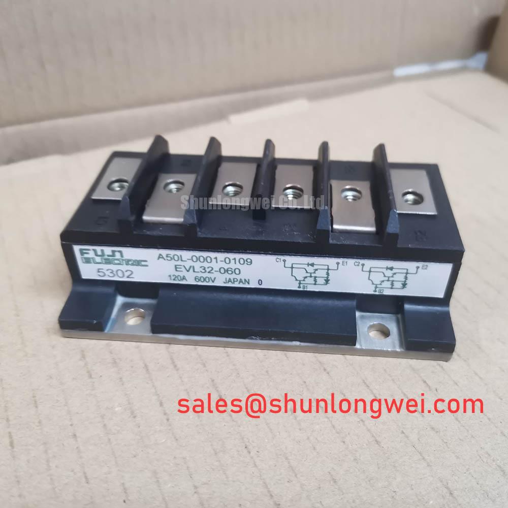
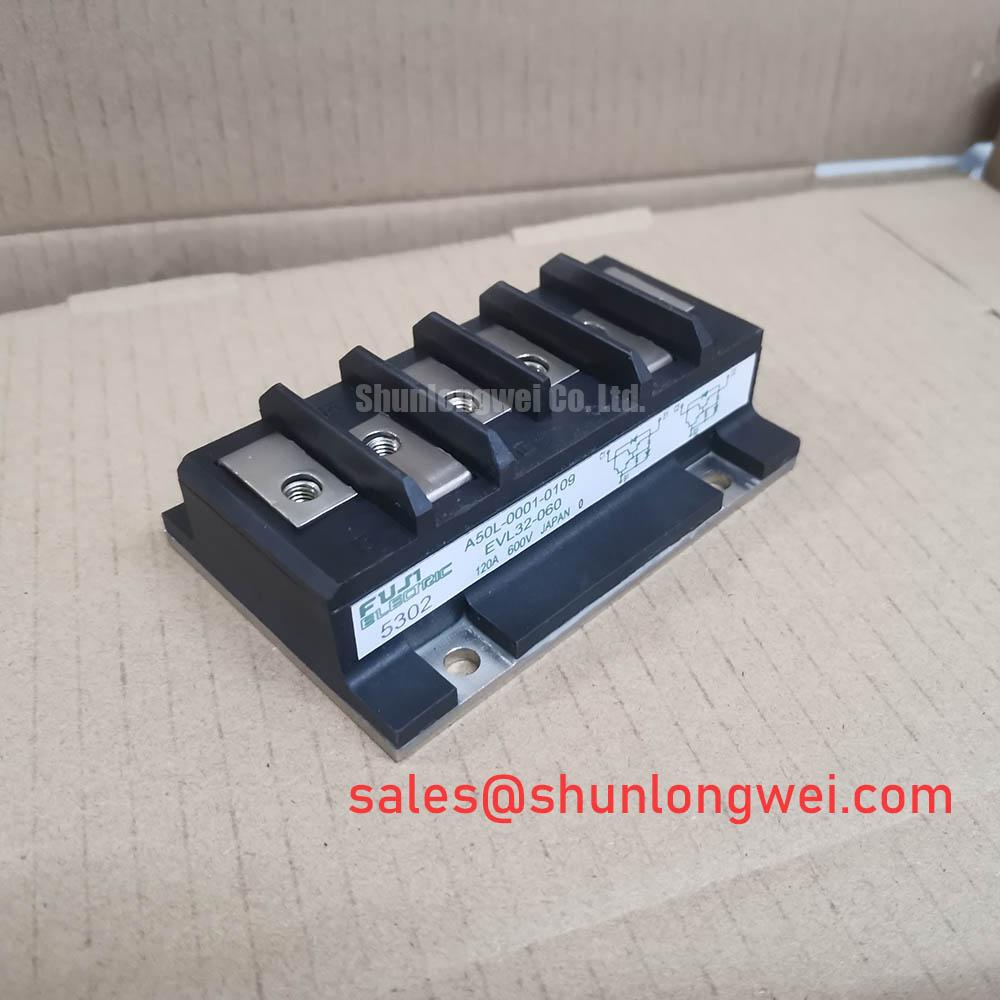
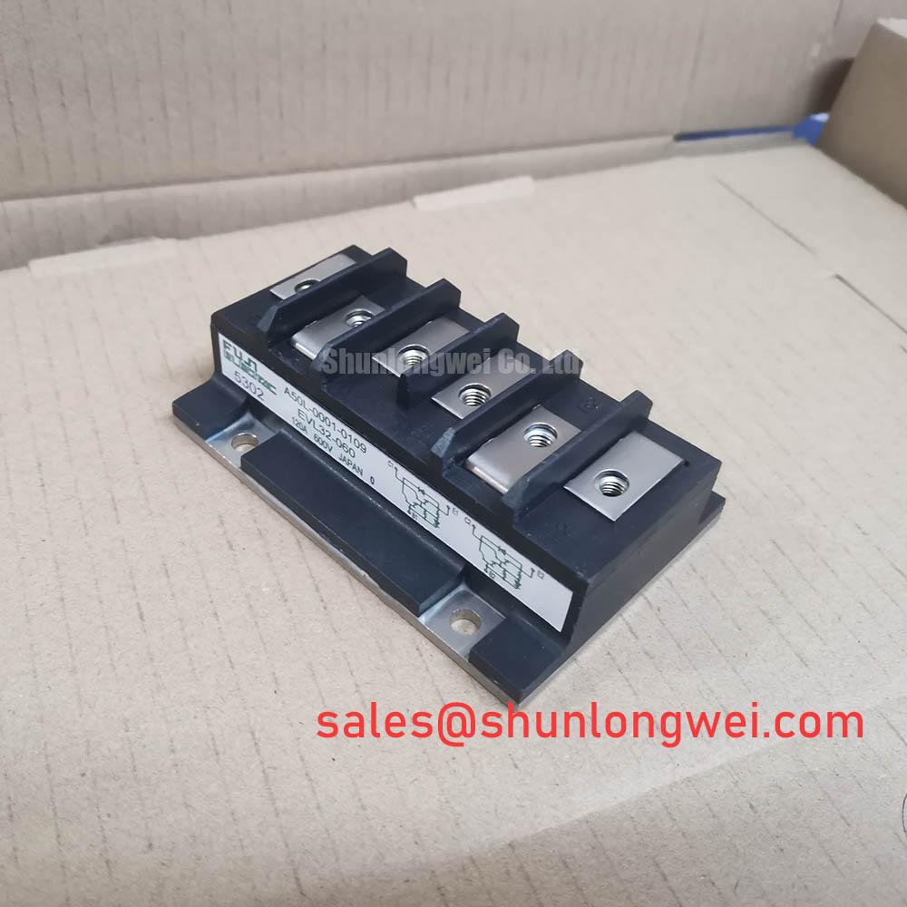
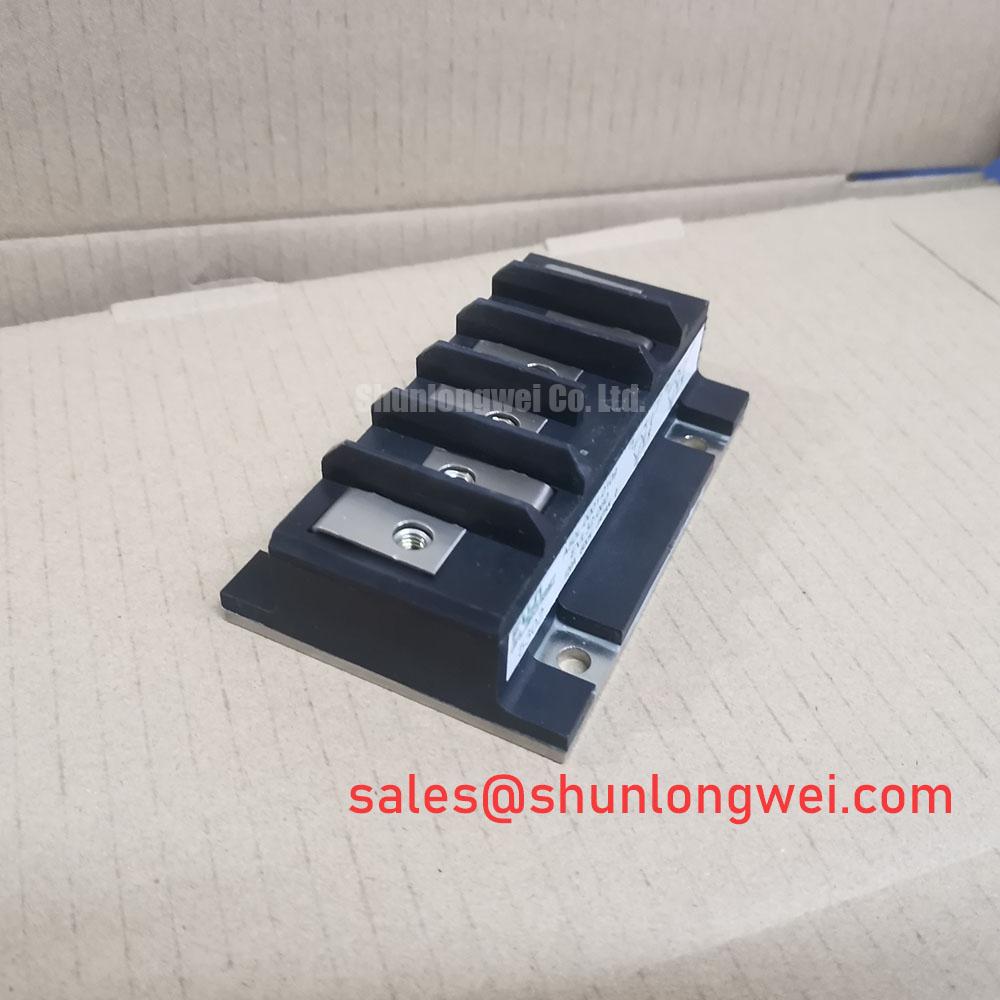
With the drive isolated and its DC link confirmed discharged, compare the installed module’s terminal markings and mounting footprint with the replacement documentation before connecting EVL32-060. Fuji Electric identifies this part as an IGBT module in a Fuji Power Module package, with a rated voltage of 600 V and rated current of 60 A (Official Specification). Those ratings establish the initial electrical boundary; they do not establish terminal compatibility, gate-drive requirements, or thermal suitability for a particular drive.
Start at the existing drive schematic, not at a generic gate-driver drawing. Identify the actual switch arrangement, gate and emitter terminals, driver return, and any clamp function already present. The supplied EVL32-060 specifications do not establish an auxiliary emitter terminal or prescribe a negative gate bias. Treat an active Miller clamp and negative bias as Design Considerations for a high-dv/dt bridge, subject to the confirmed module pinout and the driver’s permitted gate-voltage limits.
During a controlled commissioning test, observe the gate-to-emitter waveform of the device that is meant to remain off while its companion switches. A transient rise may warrant checking clamp-path impedance, driver return routing, probe placement, and switching-loop layout before attributing the event to the module. Keep the clamp connection short where the verified terminal arrangement permits it; the system engineer should confirm its effectiveness under the drive’s actual bus voltage and switching conditions. The Fuji Electric Power Semiconductors Portal provides manufacturer context for power-module integration, while the specific EVL32-060 terminal documentation should govern the connection check.
Pro Tip: Route the opposing switch paths as symmetrically as the verified terminal layout allows, then use switching measurements to check gate disturbance and turn-off voltage overshoot. For a heavy-duty variable frequency AC motor drive repair, that measurement is more useful than assuming that equal wire lengths alone produce equal switching behavior.
Transient Dynamics & Electrical Design: Thermal Time Constants and Peak Junction on EVL32-060
The 60 A current rating (Official Specification) should not be read as permission to sustain every overload pulse. A short pulse can raise junction temperature faster than the case temperature responds. Estimating peak junction temperature calls for the applicable transient thermal-impedance curve or thermal-network coefficients, the starting case temperature, and losses established for the actual switching and conduction conditions. Without those product-specific inputs, a numerical peak-temperature or overload-duration claim would be unsupported.
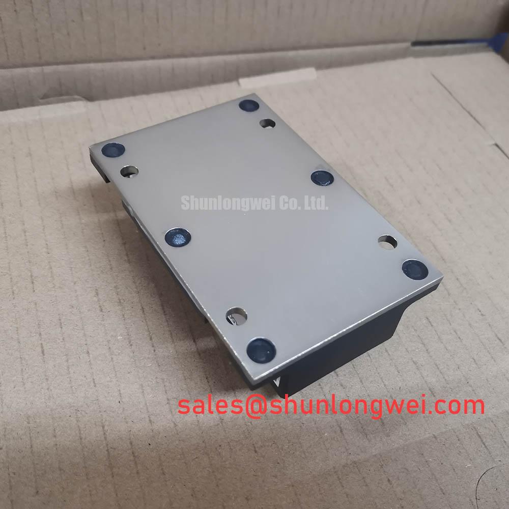
For an existing drive, record case temperature near the module’s intended measurement location and correlate it with load current, pulse duration, and cooling conditions. If the original thermal data are available, an engineer can apply their stated transient model to the measured loss profile; the resulting temperature estimate is an Engineering Calculation, not an EVL32-060 factory rating. Inspect the heatsink interface and mounting condition when measured temperature departs from the known-good drive response, while avoiding conclusions based on case temperature alone.
If the verified topology uses a bootstrap-powered high-side driver, capacitor assessment belongs to the driver circuit. Gate charge, driver quiescent consumption, leakage, switching frequency, and the longest expected high-side on-time all affect available gate-drive voltage. The supplied EVL32-060 data do not give a gate-charge figure for capacitor sizing, so retain the original circuit documentation and validate high-side supply droop during the operating sequence rather than assigning a capacitor value from the module’s voltage and current ratings.
Preventing Spurious Faults: Thermal Feedback Guidelines for EVL32-060
When a drive reports an intermittent overtemperature or overcurrent event, compare its sensor reading with an independent case-temperature measurement and the recorded load profile. Check sensor contact, wiring continuity, connector condition, and the fault timestamp before treating the module as the sole cause. The module’s thermal response, the sensor’s location, and the controller’s filtering operate on different timescales; a fault log can therefore need waveform and temperature evidence to interpret correctly.
A positive temperature coefficient of VCE(sat) can assist static current sharing in some parallel IGBT arrangements, but it must not be assumed for EVL32-060 across an unspecified operating range. This is a Design Consideration, not a published characteristic supplied for this part. Where the original equipment parallels modules, compare its documented electrical and thermal matching requirements. Symmetrical gate paths help limit dynamic imbalance, while switching tests remain necessary because static sharing does not demonstrate equal turn-on or turn-off behavior.
For repair planning, 3MBI50SX-120-02 can be placed on a comparison list, not treated as a confirmed drop-in replacement. Verify circuit topology, terminal mapping, package fit, drive requirements, and the original equipment’s ratings before considering any substitution. Where repeated thermal faults prompt an inspection of the cooling path, The Advanced Thermal Management Revolution provides broader thermal-management context without establishing EVL32-060-specific construction or performance.
EVL32-060 Circuit Protection & Reliability: Gate-Drive Loop Geometry
Trace the gate-drive return to the physical terminal shown in the verified EVL32-060 pinout. Do not assume the package exposes a separate Kelvin emitter: that feature is not established by the supplied specifications. If a documented auxiliary emitter connection exists in the installed arrangement, keeping its driver return separate from the main current path is a Design Consideration that can reduce common-emitter coupling. If it does not, assess the available return path and its measured gate waveform rather than inventing an extra connection.
Review conductor spacing, terminal insulation, and enclosure clearances against the equipment’s applicable design requirements and installation conditions. The 600 V rating (Official Specification) is a device rating, not a statement that a particular terminal layout satisfies a system insulation or EMC requirement. Likewise, any assessment involving altitude or long-term reliability needs equipment-specific operating conditions and authoritative supporting data; neither can be inferred from the module’s headline ratings.
Before returning the drive to service, capture gate-to-emitter voltage and collector-to-emitter overshoot during representative switching tests, then compare them with the confirmed device limits and the DC-link operating range. Investigate unexpected ringing through the gate loop, power-loop geometry, and measurement setup together. This leaves the protection settings and acceptable margins with the engineer responsible for the complete drive.