Content last revised on September 10, 2026
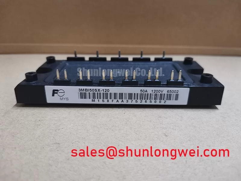
3MBI50SX-120-02 Fuji Electric 1200V 50A IGBT Module
Start incoming inspection by confirming the terminal markings against the original circuit drawing, then measure the cold-state terminal relationships with an isolated, discharged module before connecting any gate-drive or power wiring. The 3MBI50SX-120-02 is a Fuji Electric IGBT module specified at 1200 V VCES and 50 A continuous collector current at TC = 80°C. Its electrical ratings make it a candidate for evaluation in industrial inverter legs, including heavy-duty variable-frequency AC motor drives, welding converters, and induction power equipment, subject to the complete system design and thermal verification.
| Parameter | Official Specification | Engineering and QA Interpretation |
|---|---|---|
| Collector-emitter voltage | 1200 V VCES | Provides a voltage class for evaluation in systems using 540 V to 750 V DC link rails, with switching overshoot and operating conditions verified by the system engineer. |
| Continuous collector current | 50 A at TC = 80°C | Applicable to current evaluation in mid-power inverter legs when case temperature, switching frequency, duty cycle, and cooling performance are controlled. |
| Typical saturation voltage | 2.10 V at IC = 50 A, VGE = 15 V | Useful for estimating conduction loss under the stated test conditions; actual loss varies with current waveform, temperature, gate voltage, and application duty. |
| Short-circuit withstand time | 10 µs at VCC = 800 V, Tj = 125°C | Defines the stated short-circuit withstand condition and must be coordinated with desaturation detection, gate-driver delay, protection response, and controlled turn-off. |
| Package footprint | Compact SX Series | Mechanical terminals and mounting details should be checked against the original Fuji Electric documentation before layout release or replacement. |
The voltage and current values above are Official Specification data supplied for this product. They should not be treated as a complete operating envelope. A replacement assessment should also compare the original switching frequency, DC-link voltage, current profile, heat-sink arrangement, gate-driver interface, protection timing, and mechanical footprint.
Preventing Spurious Faults: Baseplate Thermal Grease Layer Control Guidelines for 3MBI50SX-120-02
Thermal interface preparation should begin with a clean inspection of the module baseplate and heat-sink contact surface. Remove old compound without scratching the mating faces, then check for raised particles, local dents, burrs, or visible curvature. A clean visual result does not prove uniform contact, so the mounting surface should be assessed with the same mechanical reference used for the original assembly.
For this module, thermal grease thickness is a Design Consideration, not an officially confirmed product parameter in the supplied data. A controlled thin TIM layer is normally preferred because excessive compound increases thermal resistance and can migrate toward nearby insulation or terminals. The stated working guideline of approximately 50 to 100 µm may be used only as an installation reference when it matches the selected compound manufacturer’s instructions. The final interface condition should be confirmed through case-temperature measurement and the system’s thermal model.
Apply the compound across the usable baseplate area without leaving dry islands or heavy ridges. Voids can create local thermal bottlenecks, while over-application may contaminate insulation distances. When the heat sink has a measurable bow, do not use mounting pressure to force the module into an unknown mechanical condition. Correct the heat-sink surface or review the approved mechanical stack-up before energizing the drive.
Mounting screws should be tightened in a staged diagonal sequence so that contact pressure develops progressively across the baseplate. The correct torque is a Design Consideration determined by the module hardware, screw size, washer arrangement, heat-sink material, and Fuji Electric mechanical documentation. After assembly, inspect the module position, terminal alignment, creepage paths, and cable strain relief. If thermal behavior changes after service, compare phase currents and case temperatures under the same load profile rather than assigning the fault to the TIM alone.
💡 Bench Tip: Keep the module and test instruments at a known cold-state condition, use ESD protection, and record a good-unit baseline before comparing diode-mode readings or terminal resistance.
Assembly Integrity & Layout Architecture: Implementing Common-Mode Transient Immunity in Harsh Industrial Drives
The gate-drive loop should be inspected as a complete switching circuit rather than as an isolated control wire. Gate and emitter conductors should follow a compact, low-noise route, while power commutation paths should be arranged to reduce parasitic inductance and unwanted coupling. The exact conductor geometry is system determined; engineers should verify peak gate-emitter disturbance and collector-emitter overshoot with an oscilloscope during representative switching tests.
Isolation between the control domain and the power domain requires careful review of the actual driver, isolated power supply, PCB spacing, connectors, and measurement method. The selected gate driver should provide a documented isolation rating and common-mode transient immunity suitable for the switching environment and applicable safety requirements; these are Design Considerations, not confirmed specifications of this IGBT module. The complete assembly still requires insulation, transient, and functional verification.
Common-mode ground bounce can appear as a false gate signal when the driver reference shifts during high di/dt commutation. Inspect the emitter reference connection, driver return path, decoupling placement, and probe connection before changing gate resistance. A negative gate turn-off bias can be considered where the driver documentation and system safety analysis support it, but the required voltage is determined by the gate-drive design and must not be assumed from this module number.
When multiple modules are operated in parallel, symmetrical busbar geometry and equal electrical path length are important Design Considerations for current sharing. The positive temperature coefficient associated with IGBT saturation voltage can support stabilizing behavior in parallel operation, but it does not remove the need to verify static and dynamic current balance. Measure each branch under controlled temperature and load conditions. If the topology includes a separate rectifier or front-end stage, engineers may also review the role of 6MBI15L-060 as a neutral reference for related power-conversion architecture, without treating it as an automatic substitute.
3MBI50SX-120-02 Operational Boundaries: Evaluating Transient Thermal Impedance Limits
The published continuous-current rating is stated at 50 A with TC = 80°C. A pulsed load cannot be judged from that value alone because junction temperature depends on pulse width, repetition pattern, conduction loss, switching loss, case temperature, and the thermal resistance of the complete mounting assembly. The 2.10 V typical VCE(sat) value applies at IC = 50 A, VGE = 15 V, so it can support a first conduction-loss estimate only under comparable electrical conditions.
For a pulsed overload assessment, use the manufacturer’s transient thermal impedance curves and the actual duty cycle. An Engineering Calculation can combine the power pulse profile with a multi-RC junction-to-case network to estimate the transient junction-temperature rise. That result remains conditional on the accuracy of the thermal model, TIM layer, mounting pressure, heat-sink temperature, and cooling airflow. The system engineer should verify peak junction-temperature margins by measurement or validated simulation before approving repetitive overload operation.
Thermal troubleshooting should compare phase current, switching waveform, case temperature, and cooling performance at the same operating point. A hot case does not identify a single root cause; possible contributors include excessive conduction loss, switching overlap, poor baseplate contact, unequal current sharing, blocked airflow, or inaccurate temperature sensing. Inspect the thermal interface after removing the module and compare the contact pattern with the mechanical installation record.
Switching loss also deserves attention when a drive operates at elevated frequency. The module’s short-circuit rating is specified at 10 µs, VCC = 800 V, and Tj = 125°C, but this is a protection boundary rather than a continuous overload permission. The DC-link voltage, gate resistance, driver delay, fault response, and load current must all be included in the protection review. The general switching and braking relationship can be cross-checked through this reference on braking resistor and chopper circuit calculation.
Transient Dynamics & Electrical Design: High-Speed Fault Management and VCE Desaturation
Desaturation protection should be coordinated with the module’s stated 10 µs short-circuit withstand time. The driver must detect an abnormal collector-emitter condition, blank the detector only as required by the switching event, and begin a controlled turn-off before the withstand interval is consumed. The complete delay budget includes sensing, blanking, logic propagation, gate discharge, and the effect of stray inductance.
A two-stage soft turn-off sequence is an Engineering Recommendation for reducing the abrupt current interruption that can produce inductive collector-emitter overshoot. The first stage can limit the rate of gate discharge, while a subsequent stage completes turn-off after the fault energy has been controlled. The actual timing and gate-current profile are system determined. Verify the collector-emitter peak against the DC-link voltage and the module’s voltage rating during short-circuit and hard-switching tests.
Gate-loop inductance, Miller plateau behavior, and reverse-recovery current from the freewheel path can interact during a fault or commutation event. The diode reverse-recovery softness factor is not provided in the supplied product data, so EMI behavior and voltage overshoot should be measured in the finished converter rather than inferred from a generic diode description. Active clamping may be evaluated when the measured transient approaches the system voltage margin, provided that the clamp network, gate driver, and protection logic are tested together.
For incoming QA, confirm terminal polarity from the original documentation, use a properly isolated low-energy measurement setup, and compare diode-mode forward readings with a known-good reference under the same instrument range. A reading that differs from the reference may indicate a connection issue, measurement-path influence, or device damage; it should be followed by controlled insulation and gate-terminal checks rather than a single-value pass or fail decision. The Fuji Electric power semiconductor and IPM resource provides broader manufacturer context for related semiconductor products.
For replacement evaluation, the 6MBI300U-120 may be reviewed as a separate Fuji Electric module for comparison of voltage class, current rating, package, and circuit topology. It should not be treated as a direct replacement without confirming electrical ratings, terminal arrangement, gate-drive requirements, thermal mechanics, and protection behavior. During final drive commissioning, the practical reference for gate-loop control and fault verification is Precision Gate Drive Design.