Content last revised on September 19, 2026
7MBP300RA060 Circuit Protection & Reliability: Calibrating Fault-Clearing Dynamics
Short-circuit protection should be evaluated as a complete control loop rather than as an isolated driver feature. The service engineer should identify where desaturation or overcurrent sensing is implemented, determine how the fault signal reaches the controller, and confirm whether the original design uses a staged turn-off sequence. The supplied product information confirms the module’s 600.0 V voltage rating and 300.0 A current rating, but it does not provide a universal short-circuit withstand time, SCSOA limit, desaturation delay, or prescribed soft turn-off profile. Those values must be verified in the Fuji Electric documentation and the equipment-level protection design.
A two-stage turn-off approach is commonly evaluated when the power stage must interrupt a severe fault without creating excessive collector-emitter overshoot. The first action reduces the gate-drive energy and limits the current transition rate; a subsequent controlled turn-off can reduce the risk of abrupt commutation. This is a Design Consideration, not an official operating guarantee for this model. The final timing must be established from short-circuit testing, the actual gate driver, DC-link impedance, and the protection circuit’s propagation delay.
During commissioning, use an isolated differential probe and a current measurement method suitable for the expected pulse amplitude. Compare the collector-emitter waveform, gate-emitter waveform, and fault response on a known-good assembly. A fault that appears only during cable connection, regenerative braking, or a high-load transition may involve parasitic inductance, measurement-ground coupling, gate-drive instability, or an incorrect protection threshold. Avoid assigning a single cause before checking the entire switching loop.
Clearance and creepage around the high-voltage terminals should follow the applicable equipment insulation standard and the pollution environment. The module’s rated voltage alone does not define the required board or busbar spacing. Designers should verify the enclosure, altitude, contamination level, coating policy, and working-voltage definition before finalizing the mechanical layout. If the module is evaluated for electric forklifts or warehouse traction inverters, the service review should include battery voltage variation, regenerative events, contactor sequencing, and the possibility of long motor leads.
For a broader application context covering industrial converter use, engineers can consult the Industrial Applications reference. A neighboring power-stage product such as 6MBI100L-060 may be useful as a catalog reference during topology comparison, but electrical interchangeability must not be assumed from voltage or current labels alone.
7MBP300RA060 Thermal-Electrical Optimization: Optimizing Heatsink Contact Pressure and Practical Tuning
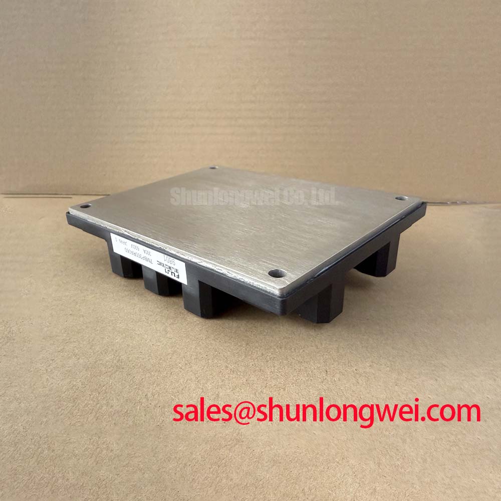
Before energizing a replacement, clean the heatsink contact surface, inspect the mounting plane, and confirm that the thermal interface material is distributed evenly without trapped contamination. The module package is supplied only as “Module” in the available product data, so the exact baseplate flatness, permitted interface material, mounting-hole arrangement, and manufacturer torque sequence should be taken from the relevant mechanical drawing. A general mounting method is a Design Consideration and must not be represented as a Fuji Electric specification.
Uneven contact pressure can create localized thermal resistance even when the heatsink appears adequate. A practical installation review checks the heatsink for distortion, confirms that the module sits naturally without forced alignment, and applies the fasteners in a controlled cross-pattern when the manufacturer’s instructions call for it. Thermal compound should be applied as a controlled interface layer appropriate to the selected material; its target thickness and application method are system-dependent unless explicitly stated in the product documentation. After mounting, inspect for extrusion, dry regions, or evidence that the housing has been mechanically stressed.
Electrical and thermal verification should be performed together. A 300.0 A rating does not mean that the module can continuously carry 300.0 A in every ambient condition or switching mode. Engineers should correlate phase current, conduction interval, switching loss, heatsink temperature, airflow, and case temperature during the intended duty cycle. The allowable junction temperature, transient thermal impedance, and derating curve must come from the applicable official data rather than being inferred from the headline current rating.
High-side gate-power integrity also requires attention when the module is used in a bridge inverter. If the driver uses a bootstrap arrangement, the capacitor selection should account for gate charge, driver quiescent current, refresh interval, leakage, switching duty, temperature, and the required gate-voltage stability. This is an Engineering Recommendation, not a fixed capacitor value for 7MBP300RA060. The designer should confirm that the selected driver can maintain the required gate bias during the longest high-side conduction interval and during regenerative transitions.
When an installation replaces an older power module, compare the gate-drive supply behavior rather than connecting the existing driver automatically. Check gate resistance, turn-on and turn-off paths, Miller clamp behavior if present, dead-time, fault reset logic, and the driver’s common-mode transient immunity. If the replacement changes the switching behavior, the heatsink test should be repeated because lower or higher switching loss can alter the thermal balance even when the external load is unchanged.
Safety Interlock Note: Isolate the DC link and wait for the equipment’s verified discharge procedure before touching the module, gate-drive connector, or measurement wiring.
Field Diagnostics & Commissioning: Auxiliary Emitter Return Trace Separation in 7MBP300RA060 Topologies
During a failed-drive investigation, trace the gate-drive return from the driver board to the module without relying on the physical proximity of copper as proof of a correct reference. A high-current emitter return can develop a transient voltage that is different from the local driver reference. If the control return shares that path, the driver may interpret common-emitter movement as a gate signal, producing ringing, false turn-on, uneven switching, or an unexpected protection event.
The recommended design principle is to keep the low-current gate-drive reference separate from the high-current commutation return until the intended reference point defined by the module and driver topology. This is a Design Consideration. The actual routing depends on the module terminal arrangement, the gate-driver isolation method, the busbar geometry, and whether the equipment uses a dedicated auxiliary emitter connection. Do not add or remove a return connection based solely on a visual similarity to another module family.
For commissioning, first inspect the gate voltage directly at the module terminals with a measurement loop that does not introduce a long ground lead. Then compare the gate waveform during no-load pulses, controlled load operation, braking, and fault response. A waveform that changes substantially when the probe reference is moved may indicate measurement-loop pickup rather than a real gate-drive defect. Verify the signal with a suitable differential measurement method and compare it with the known-good channel.
Common-mode noise can also enter through driver power supplies, isolated communication paths, shield connections, and metalwork bonding. Designers should establish a deliberate current-return path and prevent high di/dt busbar fields from crossing sensitive control wiring. Shielding and grounding arrangements should be validated during switching tests because an enclosure connection that appears quiet at low frequency may carry a significant transient current during commutation.
Long motor cables deserve a separate review. Their distributed capacitance and transmission-line behavior can reflect fast voltage edges back toward the inverter. The resulting motor-terminal and module-side waveforms may differ, particularly when cable length, termination, motor insulation, and switching edge rate change. Filtering, output reactors, or edge-rate control may be considered where the system requires them, but the choice must be based on measured voltage stress, motor requirements, thermal loss, and the drive manufacturer’s limits.
Transient Dynamics & Electrical Design: High-Frequency Commutation Loop Inductance on 7MBP300RA060
Inspect the positive bus, negative bus, module terminals, and local DC-link capacitors as one commutation loop. During a fast current transition, stray inductance produces an additional voltage proportional to inductance and di/dt; the resulting peak is added to the applied DC-link voltage and must remain within the verified semiconductor and insulation boundaries. This relationship is an Engineering Calculation principle, not a guaranteed value for the installed product. The system engineer must measure the actual peak with a suitable probe and compare it with the official voltage rating and the equipment protection strategy.
Symmetrical planar busbar geometry can reduce loop area and limit magnetic coupling between the power path and the gate-drive wiring. The preferred arrangement is determined by the module terminal positions, capacitor placement, mechanical insulation, service access, and required creepage. The supplied product data does not authorize a universal inductance target, so any value such as a sub-tens-of-nanohenry design objective must be treated as a project-specific engineering target and verified with measurement or an adequately correlated model.
Snubber selection should follow the measured ringing frequency, overshoot amplitude, pulse energy, repetition rate, capacitor dielectric behavior, resistor pulse capability, and thermal dissipation. A snubber that suppresses one operating point may increase loss at another. Designers should test across battery or DC-link variation, load current, regenerative braking, temperature, and cable configuration. If an RC or clamp network is added, confirm that it does not disturb the gate-drive reference or create an unintended high-frequency return through the control board.
Regenerative braking introduces another electrical boundary. When the motor returns energy to the DC link, the control system may use a braking chopper and resistor or another energy-management path. The resistor, chopper switch, bus capacitor, contactor, and battery interface must be assessed as a coordinated system. The 7MBP300RA060 current and voltage ratings do not specify the permissible braking energy, pulse duration, resistor duty, or DC-link rise time. Those limits require the original traction inverter design data and dynamic testing.
For electric material-handling equipment, commissioning should therefore include loaded acceleration, deceleration, repeated direction changes, and emergency-stop behavior under controlled conditions. Capture the DC-link voltage, phase current, gate waveform, and module thermal response at the same time. When the measured transient margin is inadequate, first reduce the physical commutation loop and improve the capacitor connection before selecting a clamp or changing gate resistance. Any revised switching setting should then be validated for conduction loss, switching loss, fault response, motor-cable reflection, and common-mode noise.
The 6MBI15L-060 may be reviewed as a separate catalog reference for an associated front-end or complementary power-stage discussion, but it should not be treated as a specified companion or direct substitute for 7MBP300RA060. Final compatibility remains dependent on the complete schematic, mechanical interface, driver behavior, protection timing, and verified operating conditions.