Content last revised on September 10, 2026
Technical Evaluation of the Fuji Electric 7MBR25SA120B-50 IGBT Module
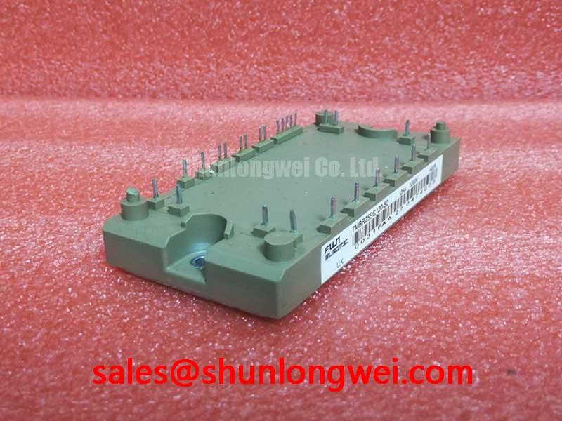
The Fuji Electric 7MBR25SA120B-50 consolidated PIM delivers a compact power stage by integrating a rectifier, brake chopper, inverter, and NTC thermistor.
Specs: 1200V | 25A | VCE(sat) (typ) 2.1V.
Key Benefits:
- Reduces footprint size via multi-chip integration.
- Simplifies heatsink coupling with localized NTC tracking.
By offering a high voltage rating, it mitigates grid voltage surges in industrial lines. For 400V inverter systems prioritizing package integration, this 1200V 25A module is the optimal choice.
Application Scenarios & Value
System-Level Efficiency in Variable Frequency Motor Drives
Engineers often face the double challenge of reducing layout stray inductance while managing space constraints in high-efficiency industrial motor controls. The Fuji Electric 7MBR25SA120B-50 addresses this directly. In a typical factory automation system, managing motor startup surge currents can stress semiconductor junctions. The rectifier section's surge current rating of 260A provides robust protection during these transient startup phases. Utilizing this PIM simplifies the design of a compact Variable Frequency Drive (VFD) or a high-precision servo drive. Engineers consulting a power semiconductor selection guide will recognize that PIMs offer significant layout advantages. Furthermore, incorporating this module in a UPS (Uninterruptible Power Supply) ensures clean power delivery because the integrated brake chopper enables controlled deceleration of inductive loads. By consolidating the power conversion stages, designers can easily comply with industrial standards like IEC 61800-3 for electromagnetic compatibility, since the compact layout reduces the loop area of high-speed switching currents. While this model is ideal for compact 2kW drives, for applications requiring higher current handling, the related 7MBR35SB120B-50 offers 35A capability, whereas the 7MBR50SB120-50 steps up current performance further to 50A.
Technical & Design Deep Dive
Maximizing Thermal Design and Switching Performance
The internal architecture of the 7MBR25SA120B-50 is built upon Non-Punch Through (NPT) technology. For an in-depth analysis of IGBT modules, understanding this architecture is essential. Unlike older PT structures, NPT-technology exhibits a positive temperature coefficient of the collector-emitter saturation voltage (VCE(sat)). What is the primary benefit of the PIM configuration? It minimizes stray inductance by placing the entire power stage on one substrate. How is thermal runaway prevented in this module? The NPT-technology's positive temperature coefficient naturally balances current distribution.
To understand this, consider the thermal resistance Rth(j-c) of the inverter IGBTs, rated at 0.69°C/W. Conceptually, thermal resistance functions like a multi-lane highway for heat. A lower resistance value provides more lanes for thermal energy to exit the silicon junction to the heatsink. This prevents localized heat jams that can degrade the silicon over time.
Additionally, the collector-emitter saturation voltage VCE(sat) acts like a toll bridge fee. Under continuous load, every ampere of collector current passing through the device must pay a voltage drop toll (typically 2.1V at 25A). Keeping this conduction toll low directly translates to minimal energy lost as heat during the conduction cycle, thereby increasing system efficiency.
The module's high short-circuit capability, defined by a square Safe Operating Area (SOA) at 10 times the rated current, provides a critical safety buffer, allowing the gate drive circuit enough time to detect a fault and safely turn off the device before thermal destruction occurs.
Key Parameter Overview
Electrical and Thermal Specifications for System Integration
| Circuit Section | Parameter Symbol | Maximum Ratings / Typical Value | Test Conditions / Notes |
|---|---|---|---|
| Inverter (IGBT) | VCES | 1200V | Continuous rating at Tj = 25°C |
| Inverter (IGBT) | IC | 25A (Continuous) / 50A (Pulse) | Continuous rating at Tc = 80°C |
| Inverter (IGBT) | VCE(sat) | 2.1V (typical) / 2.55V (max) | IC = 25A, VGE = 15V, Tj = 25°C |
| Inverter (IGBT) | Rth(j-c) | 0.69°C/W (max) | Junction-to-case thermal resistance per IGBT |
| Converter (Diode) | VRRM | 1600V | Repetitive peak reverse voltage |
| Converter (Diode) | IO | 25A | 50Hz/60Hz sine wave, Tc = 80°C |
| Brake (Chopper) | VCES / IC | 1200V / 15A | Continuous rating at Tc = 80°C |
| Integrated Thermistor | R25 | 50kΩ (typical) | NTC sensor value at T = 25°C |
Frequently Asked Questions
Resolving Common Engineering and Design Integration Queries
What is the primary difference between the 7MBR25SA120-50 and the B-series 7MBR25SA120B-50?
The "B" version represents design enhancements in internal chip layout and material optimization by Fuji Electric to improve overall robustness, while maintaining pin-compatible physical packaging.
How does the integrated NTC thermistor in the 7MBR25SA120B-50 improve system-level reliability?
The built-in thermistor provides case temperature tracking directly on the PIM substrate. This eliminates external probes and enables active thermal derating, protecting the module from overtemperature.
How does the inverter IGBT's Rth(j-c) value of 0.69°C/W impact heatsink selection?
The low thermal resistance of 0.69°C/W ensures efficient heat transfer, allowing designers to select smaller heatsinks or operate in higher ambient temperatures without exceeding junction limits.
Why does the converter section of the module feature a 1600V VRRM rating?
The 1600V rating provides transient voltage protection against AC line fluctuations and lightning surges, preventing avalanche breakdown in harsh industrial environments.
What type of gate drive protection is recommended for the 7MBR25SA120B-50?
We recommend using gate drivers with integrated desaturation protection (DESAT) to monitor VCE, ensuring the drive circuit shuts down the IGBT within 10 microseconds during an overcurrent event.
Deploying integrated PIM solutions like the 7MBR25SA120B-50 aligns with the broader industrial shift toward decentralized automation and high-efficiency inverter systems. By shrinking the power electronic footprint, OEMs can deliver modular machinery that fits tight modern factory envelopes. The combination of optimized thermal transfer, rugged short-circuit behavior, and a highly integrated silicon layout ensures that industrial systems remain reliable over long service lifetimes while maintaining high energy conversion standards.