Content last revised on September 28, 2026
Preventing Spurious Faults: Busbar Geometry and Switching Overshoot for MG30G2CL3
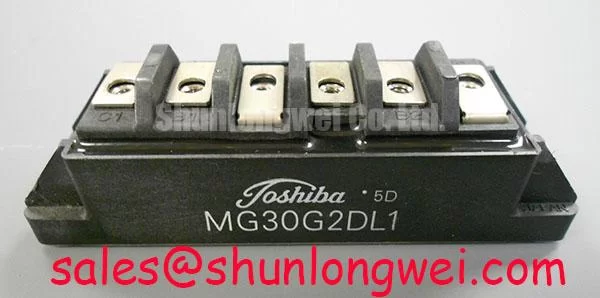
A compact industrial inverter or high-speed CNC spindle drive is a possible integration context, subject to verification against the original equipment documentation. Before fitting MG30G2CL3, trace the existing DC-link and switching-current paths. As a Design Consideration, closely coupled outgoing and return conductors can reduce loop inductance; long, separated connections can increase the voltage observed across the switch at turn-off. The system engineer should measure that peak under representative operating conditions and assess it against the module’s 1200 V rating, including the equipment’s protection behavior.
If an intermittent overvoltage fault appears after maintenance, compare DC-link ripple, busbar joints, gate waveform, and collector-emitter voltage with the machine’s known-good records. A snubber may be evaluated where switching tests show a need, but its capacitance and placement must be determined from the actual circuit rather than from the module’s current rating alone. Parasitic capacitances also affect switching-waveform interpretation; the overview of parasitic capacitance provides background, not model-specific MG30G2CL3 values.
Assembly Integrity: Heatsink Contact and Gate-Drive Layout
Inspect the heatsink for debris, damage, and uneven contact before mounting the Toshiba Module. As a Design Consideration, apply thermal interface material uniformly, avoid trapped voids, and follow the equipment and module mounting instructions for surface condition, fastener sequence, and torque. No MG30G2CL3-specific interface thickness or tightening torque is established by the supplied ratings. Record the condition of the removed interface so later maintenance can distinguish progressive deterioration from an installation change.
Keep the gate-drive return path controlled and check the installed gate resistor against the original circuit documentation. Drive sourcing and sinking capability, resistor value, and switching losses are system-dependent; adjusting one to quiet ringing can alter the others. Capture gate and collector-emitter waveforms during supervised commissioning rather than treating a reduced audible noise level as proof of adequate switching margins.
Maintenance note: Isolate and discharge the DC link before touching module terminals, then monitor contact temperature and verify that heatsink airflow remains unobstructed during scheduled checks.
Assembly Integrity: Symmetrical Connections and Replacement Evaluation
Where an assembly uses parallel switching paths, inspect conductor length, joint condition, and gate-return routing on each path. Symmetry is a Design Consideration for limiting differences in transient behavior; the 30 A MG30G2CL3 rating does not, by itself, establish a safe parallel-current-sharing arrangement. Do not assume a particular temperature coefficient for this model without its electrical-characteristics data. Compare measured path behavior with the original design and resolve unequal connections before making any resistor changes.
For a repair-material review, MG100Q1ZS40 can be included as a separate candidate for documentation comparison, not a confirmed substitute. Verify circuit topology, terminal assignment, mechanical fit, gate-drive requirements, and thermal limits before considering any change of part number. In the surrounding power circuit, MG150Q1JS40 is another device for topology review; its role and compatibility must be established from the equipment schematic, not inferred from its Toshiba model name.
Transient Dynamics: Voltage Margin and Site Conditions
For MG30G2CL3, the actionable voltage boundary supplied here is its 1200 V rating (Official Specification). A site-specific DC-bus limit cannot be calculated from that figure alone. As a Design Consideration, assess steady DC-link voltage and measured switching overshoot together, then have the system engineer determine the operating margin using the full device documentation and the equipment’s actual conditions. If the installation is at altitude or subject to unusual environmental exposure, obtain applicable manufacturer guidance before assigning a derating.
Cosmic-ray effects and single-event burnout are specialist reliability topics, but no MG30G2CL3-specific failure-rate or altitude data is established here. They should not be converted into a predicted service life or a numerical repair threshold. For practical fault prevention, trend heatsink condition, inspect terminal joints, check for moisture or condensation, and compare switching captures after a fault with earlier machine records. The article Unlocking Efficiency in Industrial Drives offers broader drive-switching context; it does not identify MG30G2CL3 as using that technology. Likewise, ROHM’s IGBT technology overview is background on device families, not a Toshiba specification.