Content last revised on October 4, 2026
Field Diagnostics & Commissioning: Long Motor Lead Reflected Wave Voltage in 7MBR30SA060 Topologies
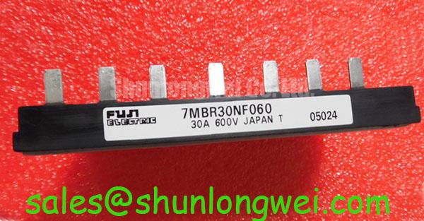
Verify the nameplate against 7MBR30SA060, inspect the module body and terminals, and confirm the application voltage before connecting a replacement unit. Fuji Electric identifies this device as a 600 V VCES Converter Inverter Brake power module with a 30 A inverter collector-current rating and a 175 °C maximum junction temperature. The stated topology is CIB, making the part relevant to compact motion-control power stages when the original circuit and mechanical interface are also compatible.
For a precision stepper or BLDC motor servo actuator, begin commissioning with the DC-link voltage, gate-drive timing, motor-cable routing, and protective-earth arrangement documented. The module’s official 600 V collector-emitter rating is an electrical boundary, not permission to operate at that value continuously under every switching, thermal, and transient condition. The system designer should verify peak collector-emitter voltage with a properly rated differential probe during acceleration, deceleration, and fault recovery.
Long motor leads can behave as transmission-line elements. An impedance mismatch between the inverter output, cable, and motor can produce reflected-wave voltage at the motor terminals and elevated switching stress at the module. A commonly discussed worst-case approximation can approach twice the incident step voltage, but the actual result depends on cable construction, length, switching edge rate, termination, motor impedance, and measurement bandwidth. Treat this as a design consideration rather than a guaranteed characteristic of this Fuji Electric module.
When an actuator shows intermittent overvoltage trips or unexplained gate-drive faults, compare oscilloscope traces at the module output and motor terminals. Check whether the disturbance is synchronized with turn-on, turn-off, braking, or cable reconnection. The corrective path may include a dv/dt filter, output choke, revised cable routing, or slower switching, but the choice should be made from measured overshoot, motor insulation limits, control-loop response, and thermal results. Keep the high-current commutation loop compact and separate from encoder, resolver, and gate-signal wiring.
The 1200 V CoolSiC™ MOSFET Advantage in Three-Phase Power Conversion article provides useful background for comparing switching behavior and voltage-margin decisions at system level. It should not be treated as a specification for this Fuji Electric CIB module. For converter installation and operating practice, engineers can also consult the IEC 60146 Semiconductor Converters Standard.
Transient Dynamics & Electrical Design: Thermal Paste Degradation Prevention for 7MBR30SA060
Thermal installation should be checked before electrical commissioning. Clean both mating surfaces, confirm that the heatsink is flat enough for the mounting system, and apply the thermal interface material as a continuous, controlled layer. Excess material can increase interface resistance, while incomplete coverage can create localized thermal concentration. The appropriate material thickness, clamping sequence, and torque must follow the module documentation and the heatsink manufacturer’s instructions rather than a generic value.
Use a progressive, cross-pattern tightening sequence so the baseplate is seated evenly. After thermal cycling, inspect for signs of pump-out, dry regions, displaced compound, or uneven contact. The official maximum junction temperature is 175 °C; actual junction temperature must be established from measured case temperature, electrical losses, thermal impedance data, switching frequency, and cooling conditions. The 30 A inverter rating also requires application-specific evaluation because current capability varies with temperature, duty cycle, pulse duration, and switching conditions.
Parallel power paths require symmetrical busbar geometry and matched current-loop impedance. A positive temperature coefficient of conduction voltage can support static current sharing in parallel semiconductor paths, but it does not automatically ensure equal dynamic current during fast switching. Gate-drive propagation, stray inductance, commutation layout, and device parameter spread should be verified with current probes and double-pulse or equivalent switching tests. The same principle applies to gate-loop damping: minimize parasitic inductance, control Miller coupling, and verify the resulting waveform rather than prescribing a universal resistor value.
Field Alert: Isolate the DC link and verify the discharge state before touching the module terminals or reconnecting gate-drive wiring.
7MBR30SA060 Thermal-Electrical Optimization: Reinforced Insulation Barrier Integrity and Practical Tuning
The supplied product data confirms the CIB topology, 600 V collector-emitter rating, 30 A inverter current rating, and 175 °C maximum junction temperature, but it does not establish a specific reinforced-isolation voltage, common-mode transient immunity value, or safety certification for the complete drive. Those values must be taken from the applicable Fuji Electric documentation and the assembled equipment’s compliance file. The module itself should not be described as independently passing a complete EMC or system safety certification.
For gate-drive integration, inspect the isolation boundary, creepage and clearance arrangement, connector contamination, and shield termination. A high common-mode transition can couple into the gate circuit through parasitic capacitance and measurement equipment. Designers should keep the isolated gate-drive return path controlled, avoid routing power-switch nodes beside logic traces, and validate gate-to-emitter voltage during the fastest system transitions. If a false trigger is suspected, compare the gate waveform with the collector-emitter transition and check the driver supply, isolation barrier, and probe reference.
Bootstrap arrangements, where used by the system, need verification of capacitor charging, diode recovery, refresh intervals, and low-side conduction time. These are system-level design conditions and are not specified by the product data supplied here. Confirm that the driver maintains the required gate voltage throughout the intended duty cycle and that startup sequencing does not leave an upper switch partially enhanced. Any proposed gate-voltage or dead-time setting should be treated as a typical starting point only and validated on the actual power stage.
Transient Dynamics & Electrical Design: Overvoltage Trip Prevention via Fast-Switching on 7MBR30SA060
The brake section of the CIB topology can be evaluated for DC-link energy management during motor deceleration. The braking IGBT and external ballast resistor must be selected from the actuator’s kinetic energy, commanded deceleration profile, DC-link capacitance, regenerative duty, resistor pulse capability, cooling arrangement, and protection thresholds. The 7MBR30SA060 topology identifies the converter, inverter, and brake functions, but the supplied specifications do not define a complete braking resistor rating or a guaranteed energy-per-cycle capability.
Commissioning should record DC-link voltage during repeated acceleration and braking events, including the worst expected load inertia and supply condition. If the voltage rises unexpectedly, inspect brake command timing, resistor continuity, brake-device gate signals, DC-link sensing accuracy, and the physical commutation loop. A fast protective trip may also reflect measurement noise, control timing, insufficient energy absorption, or switching overshoot, so the waveform should be compared with a known-good operating trace before changing thresholds.
When evaluating alternatives for a different voltage, current, or package requirement, engineers may review FS200R06KL4 as a separate device for objective parameter comparison. It should not be treated as a direct substitute without checking topology, terminal arrangement, thermal interface, gate-drive requirements, and the original equipment documentation.