
Content last revised on September 11, 2026
6DI50MA-050 Operational Boundaries: Evaluating DC-Bus Operating Voltage Headroom Derating Limits
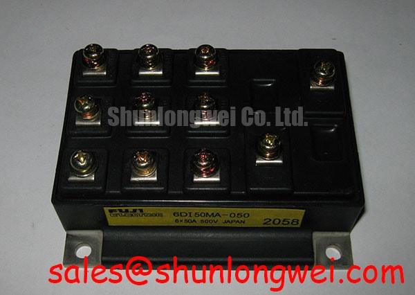
Verify the nameplate against 6DI50MA-050, then isolate the drive and perform a cold resistance comparison across the accessible power terminals before removing the existing module. Fuji Electric identifies this device as a Power Transistor Module with an official rated voltage of 600.0 V and rated current of 50.0 A. These ratings establish the component identity, but they do not by themselves confirm compatibility with a particular traction inverter, gate driver, cooling assembly, or protection circuit.
| Manufacturer | Fuji Electric |
| Part number | 6DI50MA-050 |
| Module category | Power Transistor Module |
| Rated voltage | 600.0 V, Official Specification |
| Rated current | 50.0 A, Official Specification |
For an electric forklift or warehouse vehicle traction drive, confirm the actual DC bus with a properly rated differential probe during acceleration, regenerative braking, and battery charging transitions. The 600.0 V rating is an official component specification; it is not a permission to operate a complete inverter at that voltage without checking switching overshoot, temperature, duty cycle, cooling performance, and the applicable Fuji Electric documentation.
Altitude, ambient temperature, battery condition, and enclosure airflow can change the stress seen by the power stage. Terrestrial neutron exposure and Single Event Burnout are application reliability subjects requiring a qualified reliability model and source data. No FIT rate, altitude derating curve, or SEB threshold should be assigned to this model without an authoritative datasheet, reliability report, or validated system analysis. Designers should evaluate voltage margin using measured transient waveforms and the vehicle’s real operating envelope rather than relying on a nominal battery label.
During a field inspection, compare the suspected module with a known-good signal path. Look for abnormal collector-emitter leakage, unequal phase behavior, cracked molding, loosened terminals, discoloration around busbar joints, and evidence of uneven heatsink contact. Confirm creepage and clearance against the working voltage, pollution level, enclosure condition, and applicable safety requirements. The related Fuji Electric Power Semiconductor and IPM Modules resource should be consulted for manufacturer-level product context.
Preventing Spurious Faults: Reinforced Insulation Barrier Integrity and Guidelines for 6DI50MA-050
Do not assume that a power transistor module itself provides a reinforced galvanic isolation barrier or a specified common-mode transient immunity figure. Those properties normally depend on the complete gate-drive architecture, isolation device, PCB construction, mechanical spacing, and test conditions. The system integrator should verify the required isolation rating and CMTI from the original module documentation and gate-driver documentation before approving a replacement.
In a traction inverter, route the gate-drive return according to the confirmed terminal definition and keep the high-current commutation path physically separate from sensitive control wiring. Minimize parasitic busbar inductance to reduce turn-off overshoot, then verify peak terminal voltage with an oscilloscope during the fastest expected current transition. If a snubber or film capacitor is used, its voltage rating, pulse-current capability, and physical placement must be selected from measured ringing and the complete switching topology, not from a generic module recommendation.
A sudden gate fault may involve driver supply disturbance, common-mode ground movement, connector contamination, control timing, or an incorrect terminal connection. Check the gate waveform at the module terminals, not only at the driver output, and compare it with the emitter or return reference specified by the actual circuit documentation.
6DI50MA-050 Circuit Protection and Reliability: Calibrating Transmission Line Impedance Mismatch
Long motor leads can reflect fast switching edges and create terminal stress that is different from the voltage measured at the inverter DC link. Cable length, motor impedance, termination, switching speed, and output filtering all influence the waveform. A claim that a particular cable will create a fixed multiple of the DC-bus voltage is not valid without system measurements or a documented application model.
When evaluating this module for forklift traction service, capture phase-to-phase and phase-to-ground waveforms at the inverter output and motor terminals where practical. Check whether an output choke, dv/dt filter, or other network is already installed, and verify that its current rating, thermal behavior, insulation system, and control response match the vehicle architecture. Any filter selection remains a system engineering decision and should be validated under acceleration, regenerative braking, and battery voltage extremes.
For a replacement assessment, compare the original electrical topology rather than matching only the 600.0 V, 50.0 A headline ratings. The 7MBR30SA-060-50 may be reviewed as a separate product reference, while the 7MBR10KA060 can be considered in relation to a front-end rectification or auxiliary power stage. Neither link should be treated as an automatic substitute without confirming pinout, electrical characteristics, mechanical fit, and thermal requirements.
Benchtop Waveform Tuning: Mitigating Stress via Differential Gate-Source Loop Routing
Before applying full battery power, check the gate-drive loop with the module disconnected or under a controlled low-energy test condition. The objective is to keep the gate command and its return reference tightly coupled while preventing the high-current emitter path from injecting voltage into the control reference. Whether an auxiliary Kelvin connection exists must be confirmed from the specific Fuji Electric terminal drawing; it should never be inferred from a similar-looking package.
Dead-time and interlock settings should be reviewed against the actual driver propagation delay, device switching behavior, controller timing, and measured phase-node transitions. The purpose is to prevent cross-conduction during direction changes and regenerative operation, while avoiding excessive dead-time that can increase distortion or diode conduction. Desaturation protection, soft shutdown, and short-circuit protection should be validated with the driver manufacturer’s timing data and the module’s documented short-circuit capability; no SCSOA duration or microsecond protection value is asserted here without a cited Fuji Electric specification.
Gate turn-off bias, common-mode shielding, and control-ground bonding require bench verification. Monitor the gate-to-emitter waveform directly at the module terminals during load steps and fault tests, checking for ringing, unintended pulses, and reference movement. The engineering guide Precision Gate Drive Design provides a relevant framework for this verification. Field Alert: disconnect the battery and wait for the DC link to discharge before touching the module, gate-drive connector, or busbar.