

Content last revised on September 27, 2026
95PFR80 Operational Boundaries: Evaluating I2t Sub-Cycle Melting Rating Limits
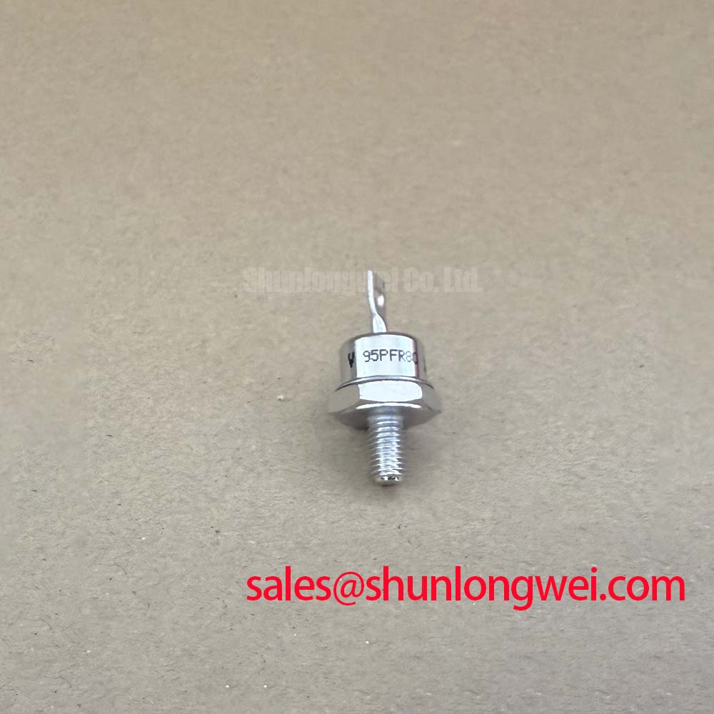
Before energizing a replacement, isolate the rectifier, inspect the stud, terminal surfaces, insulator, and case for mechanical damage, then verify the nameplate boundary of VRRM = 800 V and IF(AV) = 95 A against the equipment documentation. These are Official Specification values supplied for the Vishay 95PFR80, not calculated operating limits for every installation.
The device is identified as a DO-203AB, reverse-polarity rectifier diode. The supplied polarity description places the anode on the stud. That point must be checked against the rectifier drawing before installation, particularly where several stud-mounted devices are arranged into a bridge. A reversed connection can change the intended current path even when the mechanical fit appears correct.
The listed IFSM = 2090 A is an Official Specification for maximum surge current. It should not be interpreted as permission to expose the device to repeated short-circuit pulses or as proof that a particular semiconductor fuse will clear a fault safely. Fuse coordination requires the fuse manufacturer’s clearing I2t data, the prospective fault current, the circuit inductance, and the applicable device withstand information. The engineering check compares the fuse’s let-through I2t with the rectifier’s documented surge and thermal limits under the actual fault duration.
For a dead-short assessment, record the upstream protective device type, voltage class, prospective current, and clearing time from the machine documentation. Then obtain the current fuse coordination table for the selected protective device. If that table is unavailable, the system should not be treated as coordinated solely because the fuse current rating appears close to the rectifier current rating. The 95 A average forward-current figure describes a specified thermal operating condition and does not replace a short-circuit protection study.
The reverse package configuration also affects service wiring. Confirm that the busbar or flexible conductor does not apply side load to the stud, and check that the mating nut, washer arrangement, and heatsink interface follow the equipment or component assembly instructions. A torque value was not supplied in the stated product parameters, so the correct mounting torque must be taken from the applicable Vishay mechanical documentation and the actual fastener specification rather than inferred from the current rating.
For an urgent replacement search, engineers may also evaluate the electrically related VS-ST730C18L0 as a separate catalog option. It must be checked independently for voltage, current, polarity, package geometry, thermal data, and circuit role. It should not be treated as an automatic substitute for the 95PFR80.
Benchtop Waveform Tuning: Mitigating Stress via High-Current DC Rectifier Topologies for 95PFR80
A six-pulse bridge is a common starting topology for high-current DC rectification, while a twelve-pulse arrangement can reduce selected line-current harmonics when two appropriately phase-shifted three-phase sources and a suitable transformer arrangement are available. The 95PFR80 can be evaluated as a diode element within such a power stage, but the complete bridge rating is determined by the number of devices, current sharing, cooling, source impedance, commutation behavior, and protective coordination.
In a six-pulse bridge, inspect each current path for the same polarity orientation before applying low-voltage test power. The reverse-polarity DO-203AB configuration makes the stud and terminal identity especially important. A continuity check alone is not sufficient to validate a bridge assembly because a meter test does not reproduce reverse voltage, forward current, commutation overlap, or thermal conditions.
For a twelve-pulse rectifier, the interphase transformer and phase-shifting transformer arrangement should be reviewed with the bridge wiring diagram. Current sharing between parallel paths depends on conductor impedance, transformer leakage characteristics, device forward-voltage behavior, busbar geometry, and temperature. Designers should verify current balance by measuring each branch under controlled loading rather than assuming that identical part numbers create identical dynamic current distribution.
The specified IF(AV) = 95 A at a case temperature of 140 °C is an Official Specification value provided for this product data set. It is not a universal DC output rating for a six-pulse or twelve-pulse assembly. The allowable output current must be determined from the complete thermal path, duty cycle, line waveform, airflow or liquid cooling arrangement, parallel-device balance, and the rectifier manufacturer’s application data.
Where controlled silicon rectifiers are used elsewhere in the topology, their gate driver must be evaluated separately for IGT, VGT, pulse width, trigger repetition, and immunity to false firing. The supplied 95PFR80 information identifies a reverse-polarity rectifier diode, not a gate-triggered device. Do not assign SCR gate-drive settings to this component.
Gate driver dead time and pulse timing belong to the controlled devices and their firing controller. Designers should verify that the firing sequence prevents unintended overlap, that the trigger pulse remains valid at the worst temperature and supply condition, and that switching-node transients do not couple into the gate circuit. The final timing values must be established from the selected controlled rectifier, transformer phase displacement, commutation behavior, and oscilloscope measurements on the assembled power stage.
For a related high-power topology review, the system team can consult DDB6U180N16RRP_B37 as a separate associated device page. Its electrical role and ratings require their own verification before inclusion in a common rectifier design.
Field Diagnostics & Commissioning: Junction-to-Heatsink Heat Dissipation in 95PFR80 Topologies
When a rectifier trips on thermal protection, begin with a de-energized mechanical inspection. Check that the stud is seated squarely, the heatsink contact surface is clean and flat, the conductor does not twist the device during tightening, and the thermal interface material is spread consistently. The supplied thermal parameter is Rth(j-c) = 0.27 K/W, an Official Specification value describing junction-to-case thermal resistance under the manufacturer’s stated test conditions.
That value does not represent total junction-to-ambient performance. The finished thermal path also includes the case-to-heatsink interface, heatsink or cold plate resistance, coolant or airflow conditions, neighboring heat sources, and the enclosure environment. During commissioning, record case temperature at comparable load points and compare devices within the same bridge. A mismatch may indicate contact pressure variation, unequal current sharing, measurement placement differences, or an electrical issue that should be investigated with simultaneous voltage and current measurements.
The device’s stated IF(AV) = 95 A at high case temperature should be read together with the thermal resistance specification. It does not authorize operation at that current without confirming the case temperature and the complete cooling system. Designers should calculate the expected junction temperature from the documented thermal conditions and then validate the result using the equipment’s actual duty cycle.
Do not diagnose a failed junction from a single cold resistance reading. With power removed and all capacitors safely discharged, compare the forward and reverse measurement behavior with a known-good component and with the bridge schematic. A low reading in both directions may point to a shorted current path, but external parallel wiring can produce the same observation. Lift the appropriate connection only under an approved service procedure, then repeat the measurement while preserving the original polarity record.
⚠️ Field Alert: Disconnect the DC link and verify stored energy is discharged before removing any conductor, and use only the documented fastener torque and thermal-interface procedure for the installed heatsink.
During final commissioning, increase load in controlled stages while logging case temperature, line current, DC output, and voltage across the rectifier path. Look for abnormal temperature spread between parallel branches and for waveform distortion that changes with load. If current sharing is unstable, review busbar symmetry, transformer leakage, connection resistance, and device polarity before changing the control sequence.
The reverse stud arrangement should also be checked against insulation clearances and the mechanical envelope. The information supplied here does not specify a creepage distance, clearance value, isolation rating, or mounting torque. Those details must come from the applicable manufacturer documentation and the equipment safety design; they cannot be derived reliably from the 800 V repetitive reverse-voltage rating alone.
Transient Dynamics & Electrical Design: Coordination of Primary Spark Gaps, MOVs, on 95PFR80
Inspect the AC input protection network before exposing a replacement rectifier to line power. A primary spark gap, fuse, MOV, RC snubber, and upstream disconnect each perform a different function, and their placement must be reviewed against the actual line arrangement and surge category. The 800 V repetitive peak reverse voltage rating is an Official Specification for the 95PFR80; it is not a complete surge-qualification statement for the assembled rectifier.
MOV selection should consider the normal line voltage, tolerance, temporary overvoltage, expected surge waveform, energy capability, coordination with the upstream protective device, and the required service environment. The system designer must verify that the MOV clamping behavior remains compatible with the diode reverse-voltage boundary under the intended surge test. A MOV with a suitable catalog voltage is not automatically coordinated with a semiconductor junction.
An RC snubber can reduce high-frequency ringing caused by wiring inductance and junction capacitance, but its values must be selected from measured ringing, allowable voltage stress, pulse energy, resistor power, and capacitor impulse capability. The best starting point is a waveform measurement at the rectifier terminals using a properly rated differential probe. Any adjustment should then be validated at the worst expected line and load conditions.
Primary spark gaps require coordination with insulation spacing, follow current, ignition behavior, enclosure construction, and the applicable product safety requirements. They should not be used as a substitute for semiconductor fusing or for a properly selected MOV. If the installation is evaluated against an IEC 61000-4-5 surge test or another EMC standard, the complete equipment test plan governs; the individual 95PFR80 does not independently carry an equipment-level EMC certification.
Fast switching edges can also excite magnetic and wiring structures in the surrounding power stage. Engineers reviewing high-frequency auxiliary supplies may refer to the general discussion of ferrite core materials for high frequency switching power supplies, while remembering that core selection, saturation behavior, insulation, and thermal limits remain system-specific. Ferrite components should not be added to the rectifier path without checking their current, voltage, and pulse conditions.
For high-current electrolyzer DC rectifier equipment, the final acceptance record should include polarity confirmation, protective-device identification, thermal measurements, branch-current measurements, surge-protection inspection, and controlled-load waveform captures. A broader system architecture reference is available in The Race for Efficiency. It provides application context for modular high-power conversion, while the exact limits of the 95PFR80 must remain tied to its documented specifications and the validated rectifier design.