

Content last revised on September 19, 2026
MCD40-16IO6 Product Identification
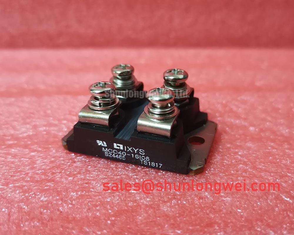
With the converter isolated and discharged, begin by checking the module marking, the TO-240AA housing for cracking or baseplate distortion, and the cold terminal to terminal readings against the original cabinet schematic before removing the failed assembly. MCD40-16IO6 is an IXYS dual thyristor module rated at 1600 V and 38 A under its official product specification. Those three verified identifiers, together with the physical housing and terminal arrangement, are the essential starting points for a repair assessment.
| Parameter | Official Specification |
|---|---|
| Manufacturer | IXYS |
| Module model | MCD40-16IO6 |
| Rated voltage | 1600 V |
| Rated current | 38 A |
| Package | TO-240AA |
| Product category | Dual thyristor module |
For a high current green hydrogen electrolyzer DC power rectifier, the module should be assessed as part of the complete controlled rectifier path rather than as an isolated current carrying part. The original firing circuit, AC source conditions, protective network, heatsink condition, fuse arrangement, and DC bus measurement points all influence whether a replacement module will operate within the measured equipment conditions. The system integrator should verify terminal identification and gate circuit connections from the original equipment documentation before energizing the rectifier.
Benchtop Waveform Tuning: Mitigating Stress via Minimizing Commutation Turn Off Voltage Stress on MCD40-16IO6
Place the removed rectifier assembly on an insulated bench and inspect every power terminal, gate connection, busbar contact face, and adjacent snubber connection before investigating switching behavior. A discolored lug, loose hardware, cracked insulating support, or overheated busbar can alter the commutation path and create a waveform problem that appears to originate inside the thyristor module. The 1600 V rating is an Official Datasheet Specification, not a statement that every observed transient voltage in a rectifier cabinet is acceptable. Oscilloscope measurements at the installed module terminals are required to establish actual peak voltage conditions.
Commutation turn off stress is normally influenced by the interaction of the supply transformer, load inductance, line impedance, diode recovery behavior elsewhere in the bridge, wiring inductance, and snubber network. Design Consideration: minimize the physical area of high current commutation loops to reduce inductive voltage overshoot during current transfer. This principle must be validated with suitable high voltage differential measurement equipment and with the actual rectifier load connected. A measurement taken only at a remote DC bus point can hide the peak stress experienced at the module terminals.
The supplied official data identifies voltage, current, and package type, but it does not provide confirmed reverse recovery peak current, recovery time, fuse clearing energy, mounting torque, or terminal torque values in the available specification set. These values must not be assumed from similarly marked modules. For a bench evaluation, compare captured gate timing, line voltage, current waveform, and terminal voltage with records from a known operating channel where available. If commutation waveform differences appear between two bridge legs, inspect the gate pulse distribution and the local RC network before attributing the condition to the replacement module.
In equipment using current feedback for firing angle regulation, poor feedback signal integrity can create unstable firing behavior that resembles a power stage commutation issue. Engineers reviewing the analogue control board can refer to ADI current sense amplifier guidance when checking the current measurement path, while the control loop itself should be assessed for correct feedback stability principles described in this operational amplifier reference. These sources support measurement planning; they do not define factory parameters for MCD40-16IO6.
⚠️ Field Alert: Do not reuse a torque value from another module family; tighten each power and mounting connection only to the original equipment or applicable manufacturer documentation after applying a uniform, thin thermal interface layer.
Preventing Spurious Faults: Surge Energy Dissipation and Clamping Volt Guidelines for MCD40-16IO6
When a rectifier trips intermittently after incoming power disturbances, inspect the protection path before changing the thyristor module. Confirm the physical condition of AC input surge components, line contactors, transformer connections, RC snubber parts, wiring insulation, and control supply grounding. A damaged MOV can lose its intended clamping function, while a degraded snubber capacitor or resistor may change the local transient response. Either condition can produce irregular firing, nuisance protection events, or recurring stress at the MCD40-16IO6 terminals.
Design Consideration: AC input surge immunity is a system property. IEC 61000-4-5 is commonly used as a surge test framework for equipment level evaluation, but the dual thyristor module itself must not be represented as independently compliant with an equipment surge or EMC standard. MOV selection and RC damping should be coordinated with the measured AC supply, expected surge environment, upstream protection, transformer characteristics, enclosure layout, and the original rectifier design. The system engineer should verify clamp behavior using the actual installation conditions rather than selecting values solely from the module’s 1600 V rating.
For repair work, first isolate whether a fault is sourced from the AC input or from the controlled bridge. Check for physical damage and continuity concerns in the surge suppression branch with the equipment safely de energized. Then examine whether the firing controller receives a stable synchronization reference and whether gate commands remain consistent across bridge positions. A gate pulse that shifts or disappears after a line disturbance may point toward a control, sensing, or synchronization path issue rather than a direct module failure.
RC components positioned close to the switching path can reduce ringing when their circuit role and placement are appropriate. Engineering Recommendation: retain the original routing, connection order, and mechanical spacing whenever replacing a failed snubber part, because additional lead length can change the result of the network. The correct resistor and capacitor values are determined by system testing and the original design documentation. No unverified clamp voltage or snubber value should be treated as an IXYS requirement for this model.
Transient Dynamics & Electrical Design: Semiconductor Protection Fuse Selection for MCD40-16IO6
A dead short investigation should begin with evidence from the whole rectifier cabinet: fuse condition, busbar marks, transformer secondary readings, load isolation results, gate driver state, and protective relay records where available. The official ratings for this module are 1600 V and 38 A, yet these ratings alone do not establish a permissible fuse clearing energy. Fuse coordination requires the module specific surge and I²t withstand information from the applicable manufacturer data, along with the selected fuse time current curve and the prospective fault current of the installed system.
Engineering Calculation is appropriate only when verified fuse and semiconductor withstand curves are available. In that case, the engineer compares the fuse’s total clearing I²t under the measured fault condition with the permissible device limit stated in the relevant manufacturer documentation. Without that source data, assigning a fuse I²t value would be speculation. The safest repair decision is to preserve the original semiconductor fuse specification and investigate why it operated, rather than fitting a larger device solely to prevent another interruption.
Check the fuse holder, contact pressure, conductor surfaces, and cable termination quality as part of this work. Heat discoloration around a fuse does not establish one cause by itself. It may be associated with poor contact resistance, overload operation, cyclic heating, a prior short event, or an unsuitable fuse characteristic. Verify the evidence in sequence: electrical continuity with power removed, mechanical condition, supply side and load side isolation, then controlled commissioning measurements. This method avoids turning a visible fuse condition into an unsupported diagnosis.
Where the original equipment documentation identifies a different module family for a comparable circuit position, engineers can review the physical and electrical documentation for the TT570N16 as a separate reference point. It is not an automatic substitute for MCD40-16IO6. Terminal layout, gate requirements, thermal interface, current duty, protective coordination, and circuit topology must all be checked by the system engineer before any replacement decision.
Assembly Integrity & Layout Architecture: Implementing Dynamic Voltage Sharing and RC Damping for MCD40-16IO6
Before mounting the replacement module, clean the heatsink interface and examine the mating surface for debris, corrosion, burrs, or uneven contact marks. A poor thermal interface can create local temperature rise and obscure the actual electrical cause of a fault. The TO-240AA package designation confirms the housing family, but it does not provide verified mounting hole dimensions, screw size, torque, terminal torque, or thermal resistance values in the supplied official parameter set. These mechanical details should be confirmed from the original hardware drawing or the complete manufacturer documentation for the installed version.
Dynamic voltage sharing is especially relevant when controlled semiconductor positions are connected in series. For parallel bridge paths, current sharing and balanced commutation are the relevant design considerations. Keep corresponding interconnect paths electrically and physically comparable so that parasitic inductance and resistance do not create unequal transient stress. RC damping and any saturable reactor used in an existing rectifier should remain associated with the circuit position intended by the original design. Their values and placement are system determined and should be validated by observing device terminal waveforms during controlled tests.
For a green hydrogen electrolyzer DC rectifier, repair teams should also verify the DC output connection, load isolation procedure, cooling path, and current feedback wiring before returning the cabinet to service. This application is a potential evaluation context, not a guaranteed application assignment for the module. The 38 A official current rating must be considered alongside the actual thermal environment, conduction duty, waveform, cooling arrangement, and the equipment manufacturer’s operating limits.
Where a repair investigation leads to a redesign discussion involving faster switching technologies, the technical context in Wide Bandgap Revolution can help frame differences in switching behavior and integration challenges. That discussion does not alter the verified identity of MCD40-16IO6 as an IXYS 1600 V, 38 A, TO-240AA dual thyristor module, nor does it replace validation of the existing rectifier’s firing, damping, fuse, and thermal interfaces.