Introduction: Beyond Magic – The Engineering Behind Instant Heat
For anyone who has used an induction cooktop, the experience feels almost magical. A pan heats up almost instantly, water boils in record time, and a gentle simmer can be maintained with uncanny precision. Unlike traditional gas or electric coil stoves that rely on slow thermal conduction, induction cooking is clean, efficient, and remarkably responsive. This rapid heating and precise control isn’t magic; it’s the result of sophisticated power electronics working silently behind the sleek glass-ceramic surface.
For design engineers and technical buyers, the challenge lies in replicating this seamless user experience reliably and cost-effectively across millions of units. The core of this challenge is managing high-frequency power conversion efficiently. The component at the heart of this entire process is the Insulated Gate Bipolar Transistor, or IGBT. This article will demystify the working principle of an induction cooktop, focusing specifically on the critical role the IGBT plays in converting raw mains power into finely controlled cooking heat.
The Core Principle: How Induction Heating Works
The fundamental principle behind induction cooking is Faraday’s Law of Electromagnetic Induction. In essence, a changing magnetic field can induce an electric current in a nearby conductor. An induction cooktop leverages this principle by turning the cooking pot itself into the heating element.
Here’s a breakdown of the process:
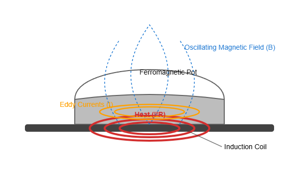
- The Work Coil: Beneath the ceramic surface of the cooktop lies a tightly wound copper coil.
- High-Frequency Current: A specialized electronic circuit drives a high-frequency alternating current (AC), typically in the range of 20 kHz to 100 kHz, through this coil.
- Oscillating Magnetic Field: This high-frequency current generates a powerful, rapidly oscillating magnetic field that extends upwards, passing through the ceramic top.
- Inducing Eddy Currents: When a ferromagnetic pot (one made of iron or certain stainless steels) is placed on the cooktop, the magnetic field penetrates the base of the pot. This rapidly changing field induces strong, circular electrical currents within the metal of the pot. These are known as “eddy currents.”
- Joule Heating: The metal of the pot has inherent electrical resistance. As the large eddy currents flow through this resistance, they dissipate energy in the form of heat—a phenomenon known as Joule heating. This heat is generated directly within the base of the pot, which then cooks the food through conduction.
This direct heating method is why induction is so efficient. Very little energy is wasted heating the air or the cooktop surface itself. However, to generate this powerful, high-frequency magnetic field, the standard 50/60 Hz mains electricity must be converted, a task performed by a power inverter circuit where the IGBT is the star player.
The Heart of the System: The Resonant Inverter and the IGBT’s Role
The induction cooktop’s main circuit is a type of switch-mode power supply. Its primary job is to take the low-frequency AC power from the wall outlet and convert it into the high-frequency AC needed for the work coil. This is typically achieved using a quasi-resonant or series-resonant inverter topology.
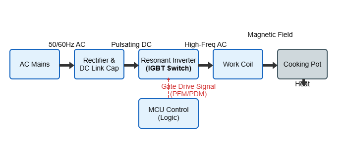
The circuit flow looks like this:
- Rectification & Filtering: The incoming AC mains voltage (e.g., 120V or 230V) is first converted into direct current (DC) by a bridge rectifier and smoothed by a large DC link capacitor. This creates a stable DC bus voltage.
- The Inverter Stage: This is where the IGBT comes in. The DC voltage is fed into an inverter, which is essentially a high-speed electronic switch. In most single-burner cooktops, a single IGBT is used in a half-bridge resonant converter circuit.
- High-Speed Switching: The IGBT is controlled by a microcontroller (MCU). The MCU sends a stream of pulses to the IGBT’s gate, turning it on and off thousands of times per second. By “chopping” the DC voltage in this manner, the IGBT creates a high-frequency square wave.
- The Resonant Tank: This square wave is then fed into an “LC tank” circuit, which consists of the work coil (the L, for inductance) and a resonant capacitor (the C, for capacitance). This LC circuit smooths the harsh square wave into a cleaner, sinusoidal-like current and helps achieve soft switching, which reduces stress and power loss in the IGBT.
The IGBT’s function is non-negotiable. It must be able to switch extremely high currents at very high frequencies with minimal power loss. Its unique structure, combining the easy gate-drive characteristics of a MOSFET with the high current-handling capability of a Bipolar Junction Transistor (BJT), makes it the ideal component for this demanding application. You can explore a detailed breakdown of this hybrid structure in our article, Deconstructing the IGBT: A Deep Dive Into Its Hybrid Structure.
Achieving Precise Firepower: How IGBT Control Translates to Heat Control
The ability to go from a rolling boil to a gentle simmer is what sets induction apart. This precise control over the “firepower” is achieved by modulating the behavior of the IGBT. The MCU adjusts the power delivered to the pot by changing how it switches the IGBT. The two most common methods are:
- Pulse Frequency Modulation (PFM): The inverter’s LC tank has a natural resonant frequency. Power transfer to the pot is most efficient when the IGBT’s switching frequency is very close to this resonant frequency. To reduce the power, the MCU shifts the switching frequency *away* from the resonant peak. This change in frequency increases the impedance of the LC circuit, which in turn reduces the current flowing through the coil and, consequently, the heat generated in the pot. Higher power settings use a frequency closer to resonance, while lower power settings use a frequency further away.
- Pulse Density Modulation (PDM) / PWM: Another effective method is to operate the IGBT at a fixed, optimal frequency but turn the entire switching sequence on and off in bursts. For high power, the IGBT switches continuously. For medium power, the MCU might switch the IGBT for 50 milliseconds and then turn it off for 50 milliseconds, resulting in a 50% duty cycle and delivering half the average power. For a very low simmer, the “on” time might be just 10 milliseconds out of every 100 milliseconds. The human eye can’t perceive this, but it results in perfectly regulated average power.
The following table summarizes the two control schemes:
| Control Method | Principle of Operation | Advantages | Considerations |
|---|---|---|---|
| Pulse Frequency Modulation (PFM) | Varies the IGBT’s switching frequency to alter the impedance of the resonant tank. | Continuous power delivery, can be quieter at some power levels. | Complex control algorithm, potential for audible noise if frequency enters the human hearing range. |
| Pulse Density Modulation (PDM) | Operates at a fixed frequency but varies the on/off duty cycle of the power bursts. | Simpler to implement, highly linear power control, operates at an optimized frequency for efficiency. | Can cause a “pulsing” or “clicking” sound at low power settings as the bursts turn on and off. |
In both cases, the IGBT’s ability to turn on and off cleanly and quickly is what enables this precise and rapid power regulation.
Selecting the Right IGBT for Induction Cooktop Designs
Choosing the correct IGBT is a critical engineering decision that directly impacts the cooktop’s efficiency, reliability, and cost. It is not simply a matter of picking the highest-rated component. Engineers must balance several key parameters:
| Parameter | Importance & Engineering Consideration |
|---|---|
| Voltage Rating (VCES) | The voltage across the IGBT in a resonant circuit can peak at 2-3 times the DC bus voltage. For a 230V AC line (which rectifies to ~325V DC), the peak voltage can exceed 700V. Therefore, IGBTs with a VCES of 1200V or even 1350V are commonly used to provide a robust safety margin. |
| Collector-Emitter Saturation Voltage (VCE(sat)) | This is a measure of the voltage drop across the IGBT when it is fully on. A lower VCE(sat) means lower conduction losses (P = VCE(sat) * IC), which translates directly to less heat generation and higher overall efficiency. In the cost-sensitive appliance market, this is a paramount concern. |
| Switching Losses (Eon, Eoff) | These parameters define how much energy is lost each time the IGBT switches on and off. Since the device is switching at over 20,000 times per second, these switching losses add up quickly. A trade-off often exists between VCE(sat) and switching speed. |
| Reverse Conducting (RC) IGBTs | Many modern designs use Reverse Conducting (RC) IGBTs. These components integrate the freewheeling diode monolithically with the IGBT chip. This saves space, reduces stray inductance, and provides a diode optimized for the resonant application, improving reliability and performance. |
| Short-Circuit Withstand Time (tsc) | This defines how long the IGBT can survive a direct short-circuit condition, such as when a pot is suddenly removed while at full power. A minimum short-circuit withstand time (e.g., 5-10 microseconds) is crucial for the protection circuitry to react and shut down the device safely. |
Finding the right balance of these characteristics is key. For consumer applications, discrete IGBTs like the BSM50GP60 or similar models are often selected for their optimized balance of low VCE(sat) and robust performance. For a comprehensive overview of available options, browsing a specialized supplier’s catalog of IGBT modules is an excellent starting point.
Common Failure Modes and Troubleshooting in Induction Cooker IGBTs
Despite being robust, the IGBT is often the first component to fail in a poorly designed or abused induction cooktop. Understanding these failure modes is key to designing a reliable product.
- Overheating: This is the most common cause of failure. It can stem from an undersized heatsink, dried or poorly applied thermal compound, or selecting an IGBT with high conduction/switching losses. The result is thermal runaway, where increasing temperature leads to increased leakage current and further heating, until the device is destroyed.
- Gate Drive Failure: An improperly designed gate drive circuit can lead to catastrophic failure. Insufficient gate voltage will fail to fully saturate the IGBT, dramatically increasing VCE(sat) and causing rapid overheating. Voltage spikes on the gate can also permanently damage the delicate gate oxide layer.
- Overvoltage: When the IGBT turns off, stray inductance in the PCB layout can cause a large voltage spike across the collector-emitter. If this spike exceeds the IGBT’s VCES rating, the device will avalanche and fail. This is why careful layout and snubber circuits are essential.
- Overcurrent/Short Circuit: If the control system fails to detect the removal of a pot or the use of improper (e.g., aluminum) cookware, the resonant circuit can draw massive currents, far exceeding the IGBT’s rating and leading to immediate failure.
Preventing these issues comes down to sound engineering practices: robust thermal management, meticulous PCB layout, and a multi-layered protection strategy within the MCU’s software. For a deeper look into this topic, our guide on IGBT Failure Analysis provides valuable insights.
Conclusion: The IGBT as the Unsung Hero of Modern Kitchens
The next time you marvel at the speed and precision of an induction cooktop, remember the unsung hero at its core: the IGBT. This powerful semiconductor acts as a high-frequency, high-power switch, masterfully converting household electricity into a controllable magnetic field. Through clever modulation of its switching behavior, engineers can grant users the precise control over heat that defines the modern cooking experience.
The selection of this single component is a critical decision, a complex trade-off between conduction losses, switching speed, voltage overhead, and cost. It is a testament to the advancements in power semiconductor technology that such powerful and efficient devices are now commonplace in our homes. For your next power electronics design, whether for consumer appliances or high-power industrial systems, ensuring you have the right IGBT solution is the foundational step toward achieving optimal performance, efficiency, and long-term reliability.