

Content last revised on September 27, 2026
Field Diagnostics and Commissioning: Braking Thermal Margins in 1SP0635V2M1-33 Topologies
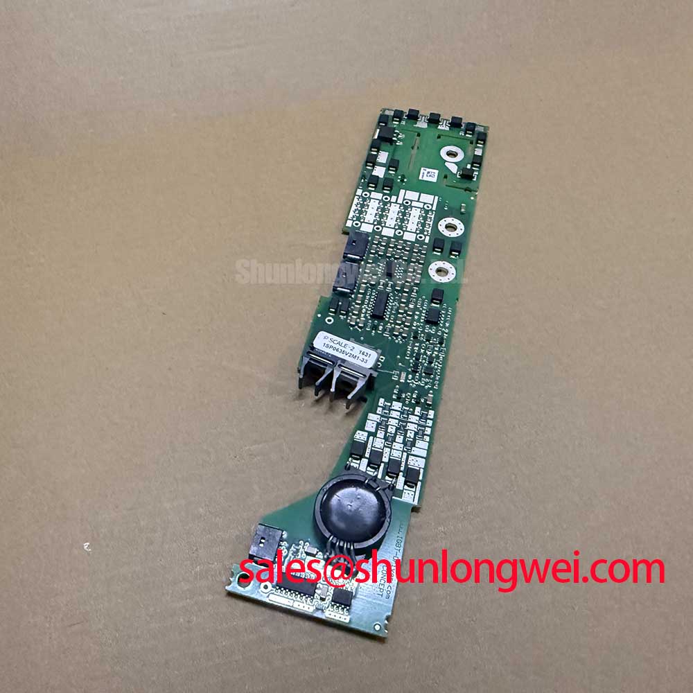
With the DC link discharged and verified safe, check the 1SP0635V2M1-33 identification against the drive documentation, then inspect its connectors, mounting points, and gate wiring before commissioning. This Power Integrations (CONCEPT) IGBT gate driver must be assessed together with the connected power semiconductor and protection circuit; its output current is gate-drive current, not motor current or collector-current capacity.
The product specifications below establish the driver’s electrical boundaries. They do not establish the braking transistor rating, resistor energy capacity, permissible DC-link voltage, or complete converter operating envelope. During equipment repair, these distinctions matter because a functioning gate driver cannot compensate for an undersized braking branch or impaired cooling.
| Parameter | Official Specification | Integration significance |
|---|---|---|
| IGBT voltage class | 3300 V | Recommended voltage class of the connected IGBT, not a prescribed DC-link operating voltage. |
| Peak output gate current | ±35 A | Peak gate charging and discharging capability, not continuous load-current capacity. |
| Isolation voltage | 6000 VAC, 1 min, 50 Hz | Specified isolation test condition, not a continuous working-voltage declaration. |
| Common-mode transient immunity | > 50 kV/µs | Driver immunity specification to consider alongside actual switching transients. |
| Switching frequency | Up to 10 kHz | Operation remains subject to the connected IGBT, driver loading, and thermal conditions. |
| Protection features | VCEsat monitoring, Advanced Active Clamping, undervoltage lockout | Protection coordination must be checked against the complete power-stage documentation. |
As a Design Consideration, begin braking checks with the equipment schematic: identify whether deceleration energy returns to the supply or is dissipated through a separate braking transistor and resistor. Do not infer an internal braking power stage from the driver designation. Compare recorded deceleration duty with the resistor’s pulse-energy documentation, transistor safe operating area, and cooling arrangement. Repeated braking can accumulate heat even when individual events appear uneventful.
For commissioning, record DC-link behavior during controlled deceleration and inspect the braking branch for loose connections, obstructed airflow, and heat-discolored terminals. A rising DC-link voltage may involve command timing, resistor continuity, switching behavior, or insufficient energy absorption; investigate these paths rather than assigning a single cause. Electrical clearance and resistor placement should follow the equipment insulation requirements and component installation instructions, with enclosure temperature included in the assessment.
Maintenance Note: Periodically compare terminal temperature trends and cooling airflow with the equipment baseline, using the equipment manufacturer’s tightening procedure before returning the drive to service. Inspect power-module thermal interfaces according to the maintenance schedule and observed thermal trends, rather than assigning an unsupported replacement interval to this gate driver.
1SP0635V2M1-33 Circuit Protection: Turn-Off Overshoot and Active Clamping
The specified Advanced Active Clamping (AAC) feature belongs in an assessment of turn-off voltage stress, but it does not remove the need to control power-loop inductance. As a Design Consideration, inspect the DC-link connections, module terminals, and return paths for unnecessary loop area. Where the equipment uses laminated or planar busbars, preserve the intended conductor overlap and spacing during repair; mechanical changes can alter switching behavior even when electrical continuity remains correct.
An Engineering Calculation explains the first-order relationship: peak collector voltage can be approximated as DC-link voltage plus stray inductance multiplied by the magnitude of turn-off current slew rate. This relationship supports waveform interpretation, not a universal inductance target. The system engineer should establish acceptable peak voltage from the connected IGBT’s limits and measured operating conditions, including bus voltage, current, temperature, and probe uncertainty.
Inspect collector voltage and gate-emitter voltage together using measurement equipment appropriate to the voltage and transient environment. A turn-off spike, ringing, or apparent clamp activity should be compared across operating points. Check the documented clamping network before changing gate resistance or adding a snubber. Snubber capacitance, damping, pulse-current capability, and dissipation require system-specific evaluation; no fixed component value follows from the driver’s ±35 A peak output rating.
Freewheeling-diode reverse recovery can influence commutation current and ringing. As a Design Consideration, compare transitions under representative current and temperature conditions, then evaluate whether changes to switching speed or damping improve voltage stress without unacceptable losses. Component-level waveform improvement does not establish equipment EMC compliance.
When tracing the upstream rectifier and DC-link charging path, the DIM800DCM17-A is a separate power-device reference for complementary-stage evaluation, not an interchangeable gate driver or a confirmed match for this converter. Its electrical role and ratings must be checked independently against the schematic. Likewise, surge-current capability, junction-temperature limits, and thermal behavior belong to the relevant power semiconductor specifications, not to the gate-driver output-current rating.
Benchtop Waveform Tuning: Isolation Conditions and Common-Mode Immunity
The 6000 VAC isolation specification for 1 min at 50 Hz and CMTI greater than 50 kV/µs describe different performance boundaries. The former is a stated insulation test condition; the latter addresses operation during common-mode voltage transitions. Neither establishes a higher immunity value, reinforced-insulation classification, or an unrestricted continuous working voltage. Equipment insulation decisions require the applicable manufacturer documentation and system safety requirements.
As a Design Consideration, inspect contamination, moisture deposits, connector damage, and routing near the isolation boundary before energized testing. After movement between cold storage and a warmer maintenance area, follow the equipment procedure for avoiding condensation before applying power. Do not conduct an improvised high-voltage isolation test on an assembled converter: connected circuitry and the manufacturer’s approved test procedure determine what can safely be tested.
During waveform checks, distinguish a genuine gate disturbance from probe pickup. Compare gate-emitter behavior, switching-node transitions, driver supply behavior, and fault indications using suitable isolated or differential measurement techniques. Keep the measurement return arrangement consistent between tests. An unexpected pulse may involve common-mode coupling, gate-loop impedance, supply disturbance, or measurement error; confirmation requires correlated traces rather than visual inspection alone.
The discussion of STMicroelectronics galvanically isolated gate drivers provides general context for isolation and driver functions, without establishing specifications for this CONCEPT product. The explanation of gate-driver functionality and the Miller effect also helps explain why collector-voltage transitions can influence the gate circuit. Actual gate bias, supply requirements, and interface assignments must come from the documentation for this exact driver and installation.
Electric material-handling and forklift low-voltage traction equipment should be considered only through a compatibility assessment, not assumed applications. The recommended 3300 V IGBT class does not establish suitability for a low-voltage traction controller; interface requirements, power-device technology, mechanical fit, and protection behavior remain decisive.
1SP0635V2M1-33 Fault-Clearing Dynamics: VCEsat Monitoring and Recovery Checks
The specified VCEsat monitoring supports short-circuit protection, while undervoltage lockout addresses inadequate driver supply conditions. Fault-clearing performance still depends on sensing connections, protection timing, the connected IGBT, and the implemented turn-off behavior. No fixed detection interval or two-stage soft-turn-off sequence should be assigned without the exact manufacturer documentation.
As a Design Consideration, distinguish a fault present at turn-on from one developing during conduction. Review detection blanking, signal filtering, and the IGBT’s short-circuit safe operating area as a coordinated system. Any fault test should use the equipment’s approved procedure and controlled energy conditions. Confirm the fault indication, gate response, collector-voltage excursion, and controller inhibit sequence before accepting the protection path.
Repeated fault resets are not a diagnostic method. Preserve event records and inspect gate connections, supply stability, load wiring, and the power stage before re-enabling operation. For parallel IGBTs, assess both static current distribution and dynamic switching balance; do not assume that temperature behavior alone guarantees sharing. Long motor cables introduce another system-dependent issue: evaluate terminal waveforms and the installed output filter rather than assigning a universal reflected-voltage multiplier to this driver.
Replacement evaluation must preserve the distinction between a driver and a power module. The SKIIP37AC12T4V1 should not be treated as a verified direct replacement for the 1SP0635V2M1-33 without documented equivalence of function, interfaces, ratings, and mounting. For broader power-stage context, Unlocking Efficiency in Industrial Drives discusses IGBT technology; it does not establish this driver’s timing or compatibility. Close the maintenance task by recording the installed driver designation, connected IGBT, protection configuration, and measured fault-response behavior in the equipment service record.