Content last revised on October 5, 2026
VI-26L-IU Circuit Protection and Reliability: Keep the Converter Separate From the Gate Loop
With the equipment isolated, measure the cold resistance across the removed converter’s input terminals and compare it with a known-good assembly before fitting the VI-26L-IU. Record the reading, inspect the connector and mounting surface, and check the equipment documentation for the required input voltage. A low reading alone does not identify a failed converter; connected input capacitors and other circuit paths can affect the measurement.
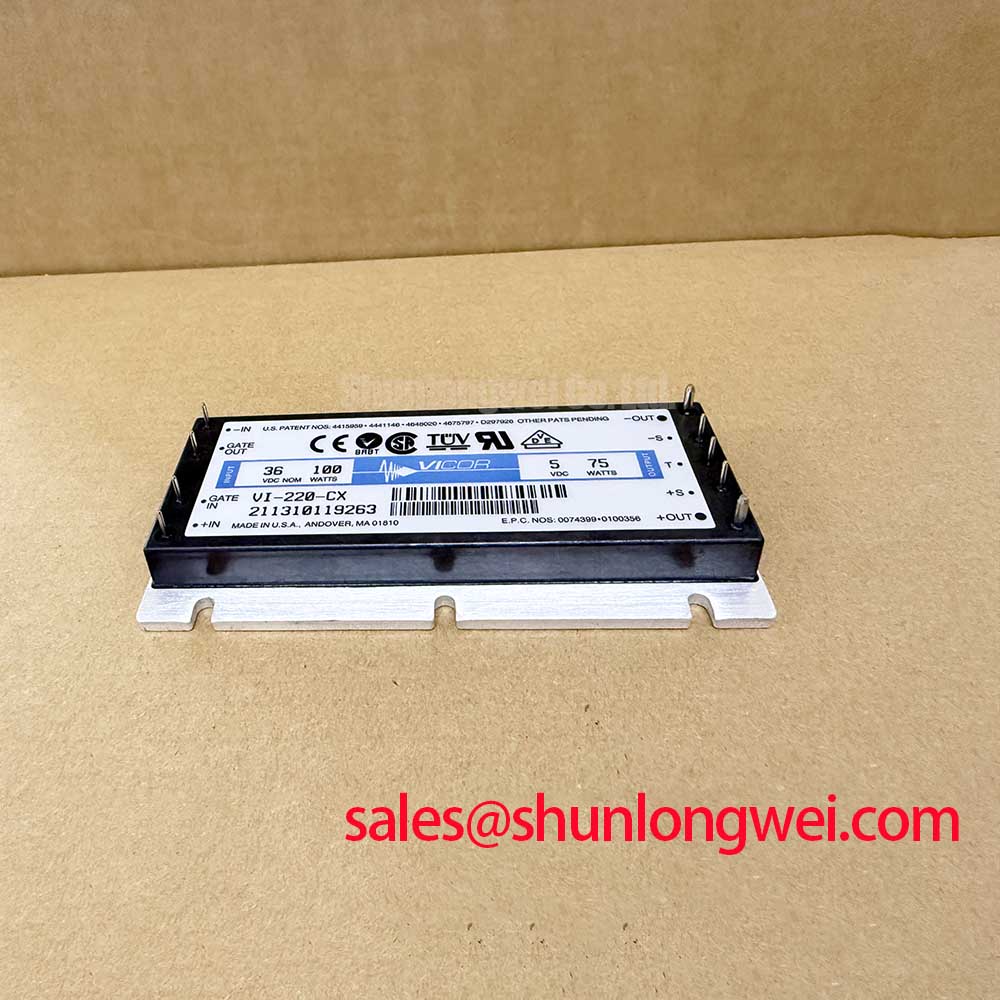
The Vicor VI-26L-IU is a Power Supply / DC-DC Converter in a brick module package. Its supplied official specification lists a 14.0 A current rating and describes its operating voltage as “Standard Industrial Rating.” That description does not provide a numeric input range. Before installation, the system integrator should verify the input range, output requirement, terminal assignments and cooling conditions against the applicable Vicor documentation and the equipment schematic.
In an inverter control cabinet, a DC-DC brick can sit near an IGBT gate-drive board without being part of the IGBT gate or emitter circuit. That distinction matters during a repair. A gate-drive fault may persist after a converter change if the actual problem lies in the driver return path, isolation interface or power-stage wiring. Conversely, a disturbance on a shared control-power rail can appear to be a gate-drive fault. A useful first separation is to check the converter’s input and output at accessible test points, then compare those observations with the driver-board fault indication.
As a Design Consideration, keep the driver’s auxiliary return from carrying main power-stage current where the original design provides separate paths. Inspect connector seating, return continuity and board damage before attributing oscillation to the DC-DC brick. Clearance between power and control conductors must be assessed from the actual assembly, its voltage requirements and the applicable equipment design rules; the package description alone does not establish an installation clearance.
A device such as the MG100Q1ZS40 belongs to a different power-device selection discussion. It is not a pin-compatible substitute for the VI-26L-IU. If the failed assembly also contains an IGBT stage, compare each device with its own schematic position and ratings rather than treating a gate-drive symptom as evidence that either part should be replaced.
Field Diagnostics and Commissioning: Separate Converter Faults From Switching Transients
After the cold checks, confirm that the incoming supply reaches the VI-26L-IU terminals under the equipment’s approved commissioning procedure. Measure the converter output at the point specified by the host schematic, and note whether a reported undervoltage occurs at startup, at load changes or during power-stage switching. Those timings help direct the next measurement, but none identifies a single cause by itself. A scope comparison with a known-good signal path can help distinguish a supply interruption from noise coupled into a fault-sense circuit.
The VI-26L-IU’s 14.0 A listed current rating is an Official Specification; it is not, by itself, a guarantee that the host assembly can draw that current continuously under every mounting or thermal condition. The repair decision also depends on the verified input range, output setting, load profile and heat-removal arrangement. Check those conditions before interpreting an output dip as an internal converter failure.
Short-circuit detection, soft turn-off, freewheeling-diode recovery and gate off-bias are properties of the surrounding power stage and its controls, not established features of this DC-DC brick. For an inverter fault that appears only when the power stage switches, review the driver and protection documentation separately. The Evolution of Negative Off-Bias Gate Drive Circuits provides background for that separate gate-drive assessment; it does not specify a gate voltage or protection timing for the VI-26L-IU.
Field Alert: Isolate and discharge the host equipment before disconnecting the brick or probing its terminals.
VI-26L-IU Operational Boundaries: Verify the Installation, Not an Assumed Altitude Rating
Commercial string inverters and micro-grid energy-storage cabinets are possible equipment contexts for evaluating a replacement control-power converter, subject to the original design. Start with the equipment parts list and the fitted module’s connection arrangement. Confirm the electrical ratings from the correct Vicor documentation, then compare mounting contact, airflow and surrounding component condition with the original installation. A matching model number does not resolve a damaged connector or an obstructed cooling path.
Do not derive a cosmic-ray single-event burnout rate, an altitude derating factor or a service-life estimate from the supplied VI-26L-IU data. No device-specific evidence for those figures is provided here. As a Design Consideration, a system engineer evaluating a high-altitude installation should review the complete equipment’s environmental and insulation requirements against documented component ratings. The same boundary applies to creepage, clearance and safety certification: these require evidence for the relevant component and assembled system, not an inference from the term “brick module.”
If the converter appears healthy on a bench but the host reports intermittent faults, inspect the installed connections before changing the diagnosis. Check for movement at the terminals, contamination around the mounting area and a voltage drop along the supply path while the equipment operates within its approved test procedure. Record where each measurement was made. A voltage observed at the upstream supply is not necessarily the voltage present at the converter terminals under load.
Preventing Spurious Faults: Check the Supply Path Before Reworking the Power Bus
Trace the VI-26L-IU’s input feed and output distribution on the host schematic before changing busbar or snubber hardware. A DC-link switching transient can disturb nearby control circuitry, but the converter’s supplied specifications do not define a permissible busbar inductance, snubber value or clamp setting. As a Design Consideration, minimize unnecessary loop area where switching currents flow, then verify measured peaks and control-supply behavior under the system’s specified test conditions. The final limits belong to the equipment design.
Keep topology discussions tied to what is actually installed. Flyback converter operation and transformer isolation and resonant converter topologies explain different switching principles; neither reference establishes the VI-26L-IU’s internal topology. Likewise, a MOV or other surge network on the host input must be checked against the host schematic rather than assumed to be inside this module.
For a replacement assessment, finish at the interfaces that can be verified: confirmed model and pin assignment, documented input and output requirements, sound mechanical attachment, and measured behavior at the converter terminals during commissioning. If a fault appears only when the inverter power stage is enabled, capture the converter supply and the relevant fault signal together. That comparison gives the repair engineer a basis for deciding whether to investigate the control-power path or the separate switching stage.