Content last revised on September 12, 2026
AA057VF02 Mitsubishi Electric TFT LCD Display Module for Industrial HMI Panels
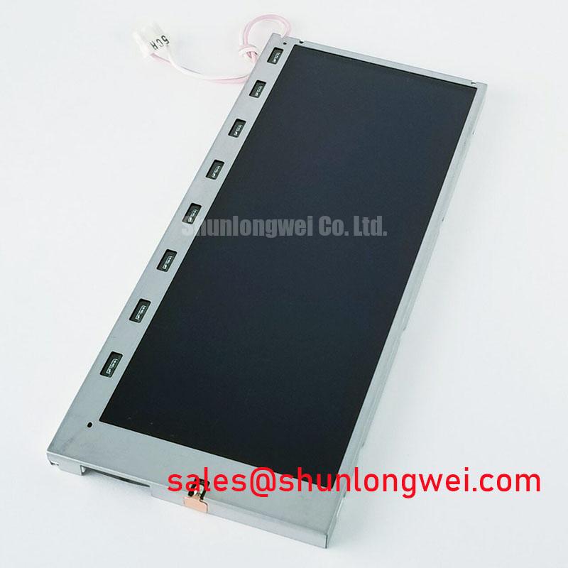
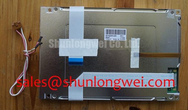
Begin the bench check with the equipment isolated from power, then compare the installed panel label, connector position, mounting outline, and visible display area with the replacement candidate before applying any signal or backlight power. The AA057VF02 is identified in the supplied factory context as a Mitsubishi Electric Industrial Grade LCD/HMI Panel in a TFT-LCD Display Module form factor. Its listed specification status is Official Factory Spec Verified.
This product page is intended for repair engineers and purchasing teams assessing a display replacement for industrial operator interfaces, machine monitoring terminals, and telematics consoles. The available factory data confirms the model identity, manufacturer, product category, and module construction. It does not provide a complete electrical pinout, active-area dimension, resolution, luminance rating, viewing-angle specification, supply voltage, backlight architecture, or timing table. Those values must be taken from the original panel documentation or the equipment manufacturer’s service information rather than estimated from a similar-looking display.
Single Vertical Hairline Defect and Sub-Pixel Column Driver Open-Circuit Localization
When an installed screen shows a single vertical line, begin by recording whether the defect remains fixed while the displayed image changes. A line that stays in the same physical location deserves inspection of the panel surface, the display cable, the connector seating, and the signal path before any panel-level conclusion is made. Photograph the symptom with a full-white field, a full-black field, and primary-color test screens. This three-screen comparison helps separate a persistent column-related symptom from an image-generation or signal-integrity problem.
A dark-shadow inspection with a flashlight held at approximately 45 degrees is a useful Design Consideration during a black-screen test. If image content can be seen faintly while the screen appears dark, the investigation should include the backlight supply, enable signal, current regulation, and connector continuity. If the line remains visible with consistent luminance while the backlight is operating, the engineer should compare the same signal path with a known-good display or test source. A cable fault, contact problem, timing issue, or panel driver connection can produce related symptoms, so the result should be treated as a localization clue rather than a single-cause diagnosis.
The AA057VF02 is documented here as a TFT-LCD Display Module, but the supplied factory information does not confirm whether a particular replacement installation uses an LED backlight, a CCFL assembly, or a separate backlight inverter. The system integrator should verify the required backlight architecture from the original panel documentation. Do not connect an unverified inverter or constant-current source to the module simply because the connector appears compatible.
Backlight ageing is also a system-level matter. Claims such as a specified half-brightness point, a fixed operating-life figure, or an MTBF curve require the applicable Mitsubishi Electric datasheet or an authoritative test report. No such numerical lifetime data is included in the available product specification, so it should not be presented as an AA057VF02 factory rating. For a field assessment, document brightness uniformity, visible local heating, driver temperature, start-up behavior, and the current waveform under the actual equipment conditions.
For a same-size or same-resolution replacement review, the LM64P10 may be included in the comparison process. It should not be treated as a drop-in substitute until the engineer verifies mechanical fit, optical characteristics, interface pin assignment, timing requirements, backlight drive method, and the host controller’s configuration.
High-Voltage Striking Potential and Secondary Coil Insulation Testing
A repair team should first identify the installed backlight circuit from the machine schematic and the original module documentation. High-voltage ignition figures sometimes associated with legacy CCFL systems must not be assigned to the AA057VF02 without a model-specific source. The supplied factory context does not confirm a 1500 to 1650 Vrms striking requirement, a secondary-coil insulation rating, a constant-current LED driver, or a 1000:1 PWM dimming capability. These values therefore remain unverified for this model.
For a suspected backlight fault, inspect the harness, connector locking features, inverter or driver mounting, and protective insulation before energizing the assembly. An insulation test, if required by the equipment service procedure, must use a method and test level approved for the complete assembly. The engineer should consider the module, cable spacing, connector construction, chassis clearance, and any connected control electronics. A generic high-voltage test can damage an otherwise serviceable panel or exceed the limits of an attached circuit.
Acoustic noise from a display assembly should be investigated at the source. Possible contributors include a backlight inverter, a magnetic component, a switching driver, mechanical resonance, or a loose mounting interface. Listen with the module installed and removed from the machine only when the service procedure permits it, then compare the sound with the driver’s switching behavior and supply waveform. A claim that a particular panel eliminates buzz cannot be made from the confirmed AA057VF02 data.
The video interface also requires documentation-led verification. The available specification does not confirm TTL or LVDS signaling, transmitter clock tolerance, data hold time, lane count, connector pinout, or timing limits across temperature. Before substitution, capture the original system’s power rails and display-control signals during start-up and shutdown. The replacement must be assessed against the host controller’s required timing sequence, not against a generic LCD interface assumption.
Power sequencing deserves particular attention where the machine has a visible white screen, an intermittent start, or a residual image during shutdown. Designers should verify the order and timing of panel supply, logic enable, backlight enable, and video data from the original equipment documentation. The acceptable sequence is system-determined and should be confirmed with measurements at the module connector. If the original controller uses a dedicated reset or display-enable signal, that signal must be preserved in the repair harness.
Industrial EMI Noise Immunity, Chassis Shielding Continuity and Common-Mode Ferrite Chokes
Pixel jitter, horizontal bands, intermittent image loss, and unstable color should be examined with the machine operating in its normal electrical environment. First compare the symptom with the motor drive enabled and disabled, then inspect cable routing, shield termination, connector pressure, and chassis bonding. A nearby variable-frequency drive can increase conducted and radiated noise, but the display symptom may also originate in the controller, grounding arrangement, power converter, or damaged signal cable.
A 360-degree shield termination is a Design Consideration for high-noise display installations when the cable and enclosure design support it. The objective is to provide a controlled return path for unwanted common-mode current while avoiding accidental ground loops or exposed shield pigtails. The correct arrangement depends on the equipment chassis, cable construction, connector backshell, and EMC test configuration. Engineers should verify shield continuity from the host controller to the display assembly with the equipment de-energized, then confirm signal quality under operating load.
Common-mode ferrite components can be evaluated when measured noise is coupled onto a display cable, but their impedance behavior must match the signal interface and data rate. Adding a ferrite without checking the differential waveform can increase edge distortion or reduce signal margin. Oscilloscope measurements at the transmitter and receiver ends are more useful than relying on the visual symptom alone. Compare the known-good signal path with the suspect assembly while observing the display clock, data transitions, supply ripple, and enable signals.
The AA057VF02 factory information supplied for this page does not include an independent EMC immunity rating or a statement of compliance for the completed machine. A display module cannot be represented as independently certified for the finished equipment’s CISPR or EN 55011 performance. The system builder remains responsible for enclosure bonding, cable selection, filtering, grounding, and final compliance testing.
Backlight thermal behavior should be checked at the installed bezel, not only on a workbench. Look for localized heating near the driver, restricted ventilation, compressed cable sections, and hot spots transferred from adjacent power electronics. Long-term static interface use can also leave image retention or uneven ageing; the severity depends on panel technology, image pattern, temperature, drive conditions, and operating time. The available AA057VF02 data does not specify a guaranteed resistance to burn-in or image retention. Screen-saver behavior, periodic image movement, and brightness control should therefore be established by the equipment designer after application testing.
For broader enclosure, grounding, and harsh-environment integration considerations, engineers can consult Industrial Display & HMI Solutions. That reference should support system evaluation rather than replace the AA057VF02 documentation or the original machine service manual.
Flush-Mount Open-Frame Bezel Integration and Perimeter Gasket Shock Isolation
Before fitting the module into a replacement bezel, place the original panel and the candidate side by side and compare the outer envelope, active viewing area, connector exit direction, fixing locations, and cable bend path. The supplied factory data identifies the AA057VF02 as a TFT-LCD Display Module but does not state its external dimensions, mounting-hole pattern, bezel tolerance, gasket compression, or fastener specification. These mechanical values must be confirmed from the original drawing.
Flush mounting should distribute mechanical load around the perimeter instead of allowing the bezel to press against the visible display area. As a Design Consideration, tighten fasteners gradually in a cross pattern only after the module is correctly seated and the gasket is aligned. The equipment designer must determine the suitable torque from the fastener size, insert material, bracket stiffness, gasket type, and panel drawing. The supplied AA057VF02 data does not authorize a model-specific torque value of 0.35 to 0.45 N·m.
During inspection, check the screen at black, white, and mid-gray fields after the bezel is secured. A local dark patch or optical non-uniformity may be related to mechanical pressure, uneven support, contamination, cable interference, or an optical assembly condition. Release the bezel load and repeat the test before identifying the panel as electrically defective. Do not press the active display area to test suspected contact problems.
Optical bonding, sealing, and dust protection should be treated as integration features only when confirmed by the panel documentation. The available specification does not verify that the AA057VF02 has a fully bonded cover lens, a defined IP sealing level, or a factory-rated moisture barrier. For a dusty or damp equipment enclosure, the system integrator should specify the external window, gasket path, drainage strategy, condensation control, and service access independently.
Cold-environment response must also be verified at system level. The supplied factory data does not establish a guaranteed gray-to-gray response at −20°C to −30°C, a heater-strip requirement, a cold-start time, or a low-temperature operating range. Liquid-crystal response can change as temperature changes, while the controller, power supply, cable, and enclosure may introduce separate limits. Engineers evaluating an outdoor telematics display in heavy mining shovels or earthmoving equipment should run the complete assembly through the intended temperature profile and check image response, start-up sequencing, condensation, connector stability, and mechanical shock performance.
⚠️ Field Alert: Disconnect equipment power and follow the service discharge procedure before inserting or removing the display cable, because live connector contact can expose signal and power pins to an avoidable electrical transient.