

Content last revised on October 25, 2026
Backlight Driving, Dimming Behavior and Flicker Suppression
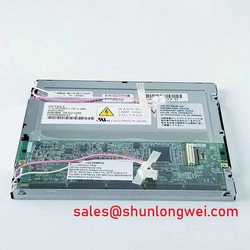
I isolate the brightness-control path from the image-data path when investigating flicker on an AA065VB02 installation. A changing backlight and unstable pixel data can produce similar complaints, but they require different measurements. With the equipment in its approved service configuration, I compare a static image at different brightness settings and observe whether the disturbance affects illumination, image geometry, or both.
Design Consideration: Backlight troubleshooting should follow the installed driver schematic and connector assignments. Measure the driver supply, enable signal, and brightness-control waveform under the conditions that reproduce the fault. Where the equipment uses PWM control, compare pulse stability with visible brightness fluctuations. Where constant-current regulation is present, assess current regulation and thermal behavior using the driver’s specified measurement method. Neither control method establishes a dimming ratio or service-life rating for this panel.
Acoustic noise deserves a separate observation. A buzz that changes with brightness can help locate the affected driver or mechanical assembly, but it does not identify a failed panel by itself. Compare the sound with electrical waveforms and check whether enclosure contact changes its intensity. Avoid disturbing energized backlight connections during this assessment.
Heat distribution also matters during extended operation. Check for obstructed ventilation and uneven temperatures around the display assembly after the equipment reaches a stable operating condition. An external temperature measurement can identify a local hot area, but it cannot establish the temperature inside the optical stack. For maintenance planning, distinguish backlight brightness depreciation from MTBF; they describe different behavior. The industrial TFT LCD technology guide provides additional background for interpreting display terminology and selection criteria.
Thermal Cycling, Polarizer Condition and Sealant Gasket Integrity
Inspect the perimeter gasket for gaps, displaced sections, and uneven compression before attributing edge discoloration to the display electronics. An enclosure gasket controls the environmental boundary of the installed assembly; its presence does not establish that the Mitsubishi Electric AA065VB02 is independently sealed against moisture or dust.
Design Consideration: Compare image behavior after thermal stabilization, using the same test pattern, viewing position, and ambient illumination. Liquid-crystal response generally changes with temperature, so motion trailing during a cold start should be assessed separately from persistent image defects. Keep environmental testing within the documented limits of the complete assembly. Record whether the effect clears as temperatures stabilize rather than assigning an unsupported response-time specification.
After moving equipment between environments, allow the assembly to reach conditions that prevent condensation before energizing it. Inspect accessible surfaces for moisture and examine the enclosure’s intended sealing and ventilation arrangements. Repeated moisture entry calls for correction of the ingress path; changing the panel alone may leave that condition unresolved.
For optical inspection, compare dark, bright, and intermediate-gray images under controlled lighting. Reflections, viewing direction, surface contamination, and mechanical pressure can each change the apparent contrast. The discussion of LCD polarizers and optical operation explains why orientation and ambient light affect the observed image. Background on optical diffusion helps distinguish illumination uniformity from pixel response without assigning an undocumented film structure to this model. Optical bonding should be evaluated as an assembly process, including adhesive compatibility and rework requirements.
Display Interface Timing, Pixel Clock and Data Mapping
Trace the installed display cable against the controller schematic before connecting an AA065VB02 replacement. Connector shape alone does not establish pin compatibility. Match the connector orientation, supply and return assignments, signal definitions, and backlight connections to the equipment’s approved wiring information.
Design Consideration: Interface troubleshooting should follow the actual signaling architecture. Differential LVDS measurements concern pair balance, termination, and receiver timing, while parallel TTL measurements concern individual logic signals and their timing relationships. These interfaces require different analysis. For an LVDS path, evaluate differential impedance against the transmitter, receiver, and cable requirements; determine the acceptable skew and clock-jitter budget from those devices and the operating pixel clock.
Capture startup behavior at the receiving connector when investigating intermittent initialization. Compare supply stabilization, signal activity, and backlight enable timing with the specified sequence. Cable movement, connector seating, and return-path continuity are useful comparison variables, provided handling follows the equipment’s isolation procedure. A single clean waveform at the controller does not establish signal quality at the panel connector.
Use fixed color and grayscale patterns to separate mapping errors from brightness problems. Incorrect bit assignments can distort colors, while timing instability can produce changing artifacts. Compare measurements with a known-good configuration before adjusting controller settings. Where the equipment exposes timing-controller or gamma adjustments, preserve the original values and follow its service procedure; arbitrary changes can obscure the fault.
For equipment compatibility assessment, surgical navigation and ultrasound display assemblies require checks beyond mechanical fit, including grayscale behavior, viewing conditions, and system validation. The TCG070WVLPCANN-AN00 can be included in a documented comparison, but direct interchangeability requires matching electrical, optical, timing, and mechanical specifications.
Thermal Expansion Clearance and Enclosure Mounting Stress
Check the enclosure opening and mounting supports for interference before tightening the display assembly. The frame should locate the module without forcing it into a distorted position. Compare the mounting drawing with the actual brackets, gasket contact, cable exit, and clearance around the bezel.
Design Consideration: Differential expansion between the enclosure and display assembly should be accommodated without transferring concentrated loads into the viewing area. Select clearances, fasteners, tightening sequence, and torque from the approved assembly requirements. A generic screw size does not establish an allowable tightening torque for this module.
Inspect uniform dark and gray images as the assembly is secured. If localized bright or dark regions change with mounting load, investigate support alignment and gasket compression before diagnosing an optical defect. Apply fastening loads progressively and evenly according to the assembly procedure, then repeat the inspection after thermal stabilization.
Maintenance Note: Periodically inspect ventilation paths and perimeter gasket condition so that dust accumulation or displaced padding does not compromise cooling or apply uneven pressure to the display.