

Content last revised on September 23, 2026
Luminance Half Life and Maintenance for the Planar EL640.480-AM1
| Product | EL640.480-AM1 |
|---|---|
| Manufacturer | Planar |
| Product Category | Industrial Grade Display Panel |
| Panel Technology | Electroluminescent panel |
| Specification Status | Limited verified product information |
Measure the panel’s illuminated field across the full viewing area and record any dark zones, unstable segments, flicker, or visible nonuniformity before removing it from the equipment. This incoming inspection is more useful than judging the panel from a small test pattern because an electroluminescent panel can show localized deterioration that is not obvious on a simple power check.
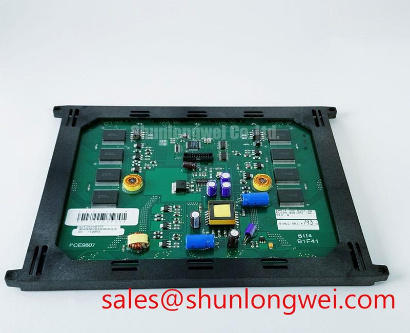
The EL640.480-AM1 is identified in the supplied factory information as a Planar industrial grade display panel using an electroluminescent panel construction. The verified product information does not provide a guaranteed luminance half life, MTBF value, shock rating, response time, viewing angle, drive voltage, or operating temperature range. Those values should not be inferred from the model number or from specifications belonging to another Planar display family.
For a replacement in a railway passenger information system or cab signalling display, compare the complete illuminated area with a known good unit under the same ambient conditions. Check for edge darkening, intermittent segments, and changes that appear after the panel has remained active. A stable image with uneven illumination can point toward the panel, its drive circuit, connector pressure, or mechanical loading, so the display should be compared with the original signal path rather than diagnosed from brightness alone.
Planar EL panels require a compatible electroluminescent drive arrangement. Do not substitute an LED constant current driver or assume that an LCD backlight controller can be connected directly. The integrator should verify the original panel documentation, drive waveform, connector assignment, and power sequencing before applying a replacement. The verified data supplied for this product does not establish a specific symmetric AC pulse range, zero DC bias requirement, charge recovery topology, or phosphor composition for this exact model.
Long term maintenance is best handled through trend records. Photograph the active panel at a fixed distance, note the equipment operating condition, and compare the same screen content during scheduled inspections. This provides a practical indication of luminance drift without assigning an unsupported lifetime figure to the EL640.480-AM1. When the display is used in a sealed control enclosure, designers should also check enclosure temperature, vibration transfer, connector retention, and contamination around the panel perimeter.
For same size or same resolution evaluation, the NL10276BC30-18 may be reviewed as a separate display option. It should be assessed independently because a different panel technology, interface, mechanical outline, or backlight arrangement can require changes to the host equipment.
Dynamic Pulse Width and Frequency Sizing for Electroluminescent Panel Operation
Probe the original display drive circuit with an appropriately rated differential measurement method and compare its waveform with the replacement panel requirements before changing pulse width or operating frequency. An electroluminescent panel is not validated by checking only the host supply rail; the panel drive waveform and connector pin function are equally important.
Symmetric AC excitation is commonly considered when integrating electroluminescent displays because balanced drive can reduce unwanted net DC stress across the panel. That is a general Design Consideration, not an official electrical rating for the EL640.480-AM1. The supplied factory parameters do not specify an approved peak voltage, frequency window, pulse width, duty cycle, or dielectric endurance limit for this model. System engineers should therefore tune only against the original equipment documentation and measured operating waveform.
When a display is dim, intermittent, or slow to illuminate, inspect the complete drive chain. Confirm that the controller is enabled, check the connector for incomplete insertion, examine the cable for crease or abrasion, and compare the panel drive waveform under load. A waveform that appears correct with the panel disconnected may change when the panel is attached, so the measurement should reflect the actual installed load and must remain within the limits of the test equipment.
Charge recovery or resonant drive techniques may be used in some electroluminescent display systems to manage switching losses. Their suitability for this Planar panel cannot be confirmed from the verified product data alone. Any adjustment should be evaluated for overshoot, ringing, electromagnetic interference, thermal rise, and visible luminance change. The final operating point is system determined and should be verified during switching tests rather than selected from a generic EL panel circuit.
The product information supplied for the EL640.480-AM1 does not confirm a sub millisecond electro optical response specification or a guaranteed cryogenic operating range. If the panel is being considered for equipment exposed to low temperature, test startup, image stability, connector flexibility, and illumination uniformity at the actual enclosure temperature. A railway cab display or passenger information terminal may also experience vibration and repeated power cycling, so the complete assembly should be tested rather than the panel alone.
The NL128102BC28-04 can be reviewed as a complementary display solution during system topology evaluation. Its electrical interface and drive requirements must be treated as separate specifications; a related product cannot be assumed to share the EL640.480-AM1 pinout or waveform.
Incoming Optical and Physical Inspection for Industrial HMI Replacement
Illuminate a uniform test image and inspect the entire active area for dead segments, stuck image elements, scratches, contamination, pressure marks, and illumination variation before connecting the panel to the final machine. Record the result with the panel’s label and connector orientation so later troubleshooting can distinguish a display fault from a host controller fault.
The verified physical description identifies the package as an electroluminescent panel. It does not confirm an anti glare coating, anti reflection treatment, touch sensor, glove operation, wet touch performance, LED backlight, optical bonding method, or front surface material. Those features should not be added to the purchasing specification unless they are confirmed by the original equipment documentation or by a controlled sample evaluation.
For high ambient light applications, evaluate reflected glare at the intended viewing angle and under the actual cabin or equipment lighting. A panel that appears acceptable on a laboratory bench can lose contrast when installed behind a protective window. Check the complete stack, including any cover lens, bezel, gasket, and mounting pressure. Do not attribute a reflection problem to the panel without examining the enclosure geometry and surrounding surfaces.
Touch functionality requires separate verification. The verified information does not state that the EL640.480-AM1 includes a resistive or capacitive touch layer. If the host equipment uses a touch overlay, confirm its active area, controller interface, calibration behavior, and response with gloves or moisture present. The panel display interface and the touch interface should be tested independently because a visible image does not prove touch communication.
Connector reliability deserves a hands on inspection. Check that the cable enters the connector squarely, that the locking feature is fully engaged, and that no contact is recessed or contaminated. Bench Tip: Use ESD protection and keep the flex cable flat and evenly aligned while closing the connector lock; never force an offset insertion.
When the display shows a blank field, compare the host enable signals and drive waveform with a known good assembly before declaring the panel defective. If image content is present but unstable, inspect cable seating, ground reference, timing integrity, and mechanical movement during vibration. The evidence should be collected at the panel connector and at the controller output so an interface fault is not mistaken for an optical fault.
Signal Compatibility and Equipment Integration Checks
Verify the installed connector pinout with the original equipment wiring diagram and continuity test before applying power to the EL640.480-AM1. The verified product data does not specify LVDS, TTL, serial, touch, backlight, or control pin assignments, and the model number alone cannot establish a compatible host interface.
If the equipment uses a differential display link, engineers may evaluate pair routing, reference return, termination, common mode range, and clock quality as general Design Considerations. A 100 ohm differential target is not an official parameter for this panel and must not be treated as a guaranteed requirement without confirmation from the panel documentation. Use an oscilloscope or suitable differential probe to compare the replacement installation with the known good signal path.
Power sequencing should also be checked at the system level. Confirm the order and timing of logic enable, display drive activation, and host image transmission from the original equipment design. Avoid connecting an unverified LED backlight supply, constant current output, or unrelated LCD inverter to an electroluminescent panel. Any protection against open load, short circuit, or overvoltage belongs to the complete driver and must be validated in the assembled system.
For a railway passenger information system or cab signalling display, mechanical fit is only one part of compatibility. Confirm the visible area, mounting points, bezel clearance, connector exit direction, cable bend path, operating environment, and service access. The available verified product information does not state the panel dimensions, resolution, viewing angle, luminance, or environmental ratings, so these attributes should be matched directly against the removed unit and the equipment documentation.
The reference on Industrial Display and HMI Solutions can support broader evaluation of enclosure sealing, vibration control, thermal management, and service practices. It should be used as an engineering reference rather than as a substitute for the EL640.480-AM1 product specification.
Power semiconductor references concerning the space charge region and depletion layer and partial discharge detection describe high voltage semiconductor or insulation phenomena. They do not establish electrical ratings, insulation performance, or certification for this display panel. Any high voltage drive assessment should use the original panel documentation, suitable measurement equipment, and system level safety procedures.
Procurement records should retain the exact Planar EL640.480-AM1 designation, the stated electroluminescent panel construction, the equipment connector information, and the results of the incoming illumination and interface checks. This gives repair engineers a traceable basis for evaluating the replacement without assigning unverified electrical or optical specifications.