

Content last revised on September 10, 2026
High Voltage Striking Potential and Secondary Coil Insulation Testing
The available factory information identifies the AA084SC01 as a TFT-LCD display module, but it does not confirm a CCFL backlight, a high-voltage ignition requirement, a secondary coil rating, or a constant-current LED input. Those values must not be assigned to this model without the original Mitsubishi Electric panel documentation. When a removed unit is connected to a separate inverter or backlight assembly, the repair engineer should identify the actual backlight technology from the equipment drawings and the original service configuration.
For a suspected CCFL arrangement, insulation testing belongs to the complete backlight and inverter assembly rather than to the LCD image panel alone. Use the approved service procedure for the equipment, isolate the inverter from control electronics, and confirm that the test instrument and applied voltage are suitable for the assembly under test. A stated cold ignition range of 1500 to 1650 Vrms cannot be treated as an official specification for the AA084SC01 from the supplied product data. The same restriction applies to claims involving a 1000:1 PWM dimming ratio, a 50,000 hour half-life, or a guaranteed MTBF.
Where the replacement system uses an LED backlight, the practical inspection changes. The technician should verify the backlight supply voltage, current regulation method, enable signal, dimming input, open-load response, short-circuit response, and fault reporting at the driver output. These are system integration properties unless they are explicitly defined in the panel documentation. A constant-current driver may protect its output under an open or shorted LED string, but the protection threshold, recovery behavior, and diagnostic signal still require confirmation from the driver documentation.
At low ambient temperature, liquid-crystal response can change and moving images may show longer transitions or visible smearing. This is a design consideration for equipment that may operate in cold service areas. The system integrator should verify the specified operating temperature, storage temperature, heater control, start-up sequence, and image performance using the original Mitsubishi Electric documentation. A heater strip must not be added solely from a general assumption about cold-weather operation; its use, control logic, and thermal effect belong to the complete display assembly design.
For a petrochemical Zone-2 operator station, the display module is only one element inside the finished protective system. The installer must separately verify enclosure certification, permitted internal heat dissipation, cable entries, creepage and clearance, and the approved service method. The LCD module itself must not be represented as independently certified for the final hazardous-area assembly.
Suppressing Localized Thermal Gradients and Monitoring Optical Color Shift
When a panel shows a dark edge, uneven brightness, or a gradual color change, begin with the supply and backlight path rather than immediately attributing the symptom to the LCD glass. Record the display condition at cold start and after normal operating temperature is reached. Inspect the driver connector, flexible cable seating, enclosure pressure points, and any local heat source near the display edges. The objective is to establish whether the change follows temperature, brightness command, mechanical pressure, or image content.
The supplied factory data does not confirm an LED backlight for the AA084SC01, nor does it provide an L70, B50, optical material, thermal spreader, or color-shift life rating. Claims about PMMA yellowing, a particular aluminum rail arrangement, or a guaranteed LED life curve therefore require a separate manufacturer source. A heat spreader can reduce local temperature concentration in some display assemblies, but its dimensions, contact method, electrical isolation, and effect on the enclosure must be determined by thermal testing on the actual equipment.
Backlight efficiency should be assessed at the driver input and at the display surface. Compare the commanded brightness with measured input power, observe current stability during start-up, and check whether brightness changes coincide with supply ripple or a protection event. If PWM dimming is used, the system engineer should verify the control frequency, duty-cycle range, minimum pulse behavior, and camera-visible flicker performance against the driver specification. The commonly discussed range of 200 Hz to 1 kHz is not an AA084SC01 factory rating and should not be used as a default setting without system validation.
High-EMI production equipment may also expose weaknesses in the display signal path. Differential traces and cable assemblies should be routed as a controlled pair, with the original interface impedance and timing requirements confirmed from the panel documentation. A value such as 100 ohms ±10 percent or a specific skew limit cannot be assigned to this model without a verified interface specification. The correct procedure is to identify whether the unit uses LVDS or another display interface, then validate signal quality at the receiving connector with a known-good assembly and an oscilloscope suitable for the interface.
When a same-size or same-resolution service candidate is being assessed, the engineer should compare more than the visible image area. Check connector position, pin assignment, mounting points, active area, controller timing, backlight control, and mechanical clearance. The Mitsubishi Electric display reference AA084VC01 may be reviewed as a separate compatibility candidate, but it should not be treated as a confirmed substitute for AA084SC01 without a documented cross-reference and bench validation.
Single Vertical Hairline Defect and Column Driver Open-Circuit Localization
A single vertical line requires controlled testing before any replacement decision. First, display a full white image and record whether the line remains fixed, changes brightness, or disappears at a different temperature. Next, repeat the observation with full red, green, and blue fields. Finally, use a black field and a mid-level gray field to determine whether the defect is a missing column, a stuck sub-pixel group, a backlight uniformity issue, or a signal-path artifact.
This field check is a practical diagnostic method, not an official AA084SC01 acceptance limit. Do not assign a fixed resistance reading or a specific diode-test value to the panel connector unless the original service manual defines it. The LCD cell, column driver connection, flexible circuit, timing electronics, and host controller can all influence the visible result. A measurement that differs from a known-good unit may indicate a connection or impedance issue, but the finding should be verified along the complete signal path.
A 45-degree flashlight inspection can help separate a surface or illumination problem from an image-generation defect. With the panel unpowered, illuminate the front surface obliquely and look for localized marks, pressure effects, contamination, or a shadow that follows the physical surface. With the unit operating, compare the same area under different solid-color fields. If the line remains aligned with the same pixel column while backlight brightness changes normally, attention should move toward the panel drive path. If the symptom follows brightness or appears as a broad dark region, inspect the backlight and diffuser area before disturbing the signal connector.
Column-driver open-circuit localization must remain non-destructive. Avoid pressing the glass edge or flexible circuit to force a temporary change, because this can alter the fault and make the subsequent inspection less reliable. Use the equipment’s approved test pattern, compare the display with a known-good signal source, and document whether the defect is present during the panel’s internal test mode if that function is available. A COG or flexible-circuit defect should only be stated when the evidence and service documentation support that diagnosis.
Life figures such as 50,000 hours to 50 percent brightness are not confirmed factory data for this product record. They must not be presented as an AA084SC01 MTBF or LED degradation guarantee. For an installed unit, maintenance planning should instead record measured luminance, operating temperature, brightness command, supply condition, and fault history. This creates useful equipment-specific evidence without inventing field failure rates or service-life predictions.
Industrial EMI Noise Immunity, Chassis Shielding Continuity and Common-Mode Ferrite Chokes
Pixel jitter and horizontal noise bands should be investigated at the point where the symptom enters the display system. Freeze the image if possible, observe whether the disturbance changes with motor speed or inverter switching state, and compare the display using the original cable path and a known-good cable. Inspect connector retention, contact condition, cable bend radius, shield termination, and the continuity between the cable shield and the intended chassis reference.
A 360-degree shield termination is a general EMC design consideration, not a confirmed AA084SC01 construction requirement. The finished equipment designer should determine the correct shield bonding method from the cable, connector, enclosure, and safety architecture. Avoid creating accidental shield loops through multiple uncontrolled grounding paths. The correct arrangement must be verified during system EMC testing, especially when the operator station is installed near variable-frequency motor drives or other high-current switching equipment.
Common-mode ferrite components can be evaluated when conducted interference is suspected, but their impedance characteristics, current capacity, placement, and effect on signal edges must be selected for the actual cable and interface. Adding a choke without checking the display timing can increase signal distortion or interfere with power-up behavior. The system engineer should compare the signal waveform before and after the component, then confirm that the display starts correctly across the required operating conditions.
For low-temperature installations, verify the panel’s documented temperature limits and observe the complete start-up sequence. Changes in liquid-crystal response, cable flexibility, driver behavior, or power-supply regulation can appear as slow image response or intermittent initialization. These observations should be correlated with measured supply behavior and signal activity rather than assigned to a single internal cause.
⚠️ Field Alert: Disconnect power and wait for the equipment’s approved discharge interval before removing the display cable or backlight connector, then confirm the connector orientation before reconnection.
When the display is part of a larger HMI replacement project, the related AA104VC01 reference may be reviewed as another Mitsubishi Electric display-system option, while its electrical compatibility remains subject to separate documentation. Broader considerations for enclosure integration, industrial display selection, and harsh-environment validation are discussed in Industrial Display & HMI Solutions. These resources support evaluation, but the original panel drawings and the finished equipment test plan remain the controlling documents for installation.
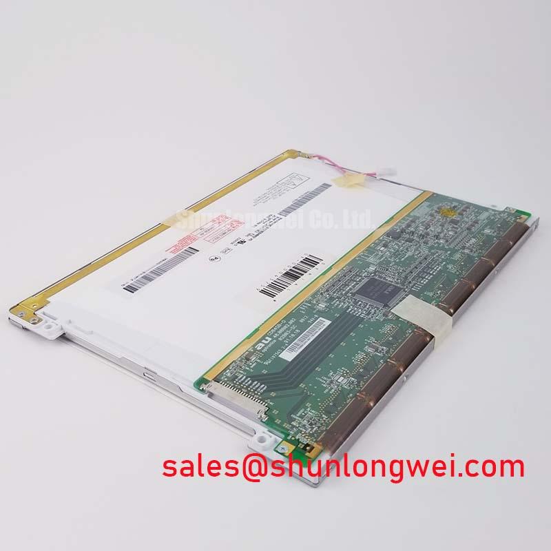
For procurement, provide the complete model marking, the equipment manufacturer and revision, the connector photographs, the failed panel symptoms, and the required delivery destination. The available product identity for this listing is Mitsubishi Electric AA084SC01 Industrial Grade LCD/HMI Panel with a TFT-LCD Display Module package. Confirm supply, interface, backlight, dimensions, and mounting details from the original equipment documentation before approving the replacement.