

Content last revised on September 25, 2026
Mitigating Gray to Gray Response Time Escalation during Cold Start Machine Power Up
For a potential installation in a harsh marine radar or navigation bridge console, the first practical check is the cold start image sequence. Record whether the display reaches a stable image, whether gray transitions appear delayed, and whether the image changes as the enclosure warms. Liquid crystal response is temperature dependent, so a slow gray transition during a cold start should be evaluated as a system behavior rather than assigned to the panel alone. The controller timing, source signal stability, backlight startup, enclosure temperature, and previous operating state can all affect the observed result.
The AA084VC07 product record does not provide a verified operating temperature range, gray to gray response specification, contrast value, sunlight readability rating, or anti glare coating specification. A marine equipment integrator should therefore verify those characteristics in the original panel documentation before approving the unit for direct sunlight or cold outdoor service. A stated contrast target, such as performance above 500:1 at a defined illumination level, must not be treated as an AA084VC07 factory specification without a corresponding Mitsubishi Electric source.
During evaluation, use the same image source and timing configuration as the original equipment. Check a moving grayscale test pattern, a dark navigation screen, and a high brightness daylight screen while monitoring the panel supply and display enable behavior. If the transition lag changes with temperature, compare the result with a known good display and verify the source timing at the panel connector. This approach helps separate liquid crystal response behavior from a controller frame timing issue or an unstable power rail.
Perimeter sealing and enclosure protection also require system level verification. Salt spray exposure, condensation, pressure on the bezel, and uneven chassis loading can affect long term display reliability, but the available product information does not establish a marine certification or sealing rating for this model. Designers should evaluate the complete enclosure, gasket arrangement, ventilation path, and service access rather than attributing environmental protection to the LCD module itself.
TTL Digital RGB Bus Synchronization and Logic Power Rail Verification
Before connecting AA084VC07 to a replacement controller, identify the original interface from the equipment schematic and cable assembly. The supplied product information does not confirm whether this model uses TTL RGB, LVDS, a specific bit depth, a JEIDA mapping, or a VESA mapping. The system integrator should verify the required supply voltage from the original panel documentation. Do not connect a 3.3 V or 5.0 V rail based only on a connector similarity or on the voltage used by another Mitsubishi Electric display.
For a TTL design, verify the relationship between pixel clock, data enable, horizontal timing, vertical timing, and the red, green, and blue data groups. For an LVDS design, inspect differential pair polarity, lane order, clock placement, and data mapping. A split image, incorrect color grouping, unstable sync, or a panel that remains blank may indicate a mapping or timing mismatch; verify the signal path with an oscilloscope and compare it with the known good assembly rather than assigning one cause without measurement.
Differential routing principles remain relevant when the controller uses a differential display link. The designer should maintain a controlled and consistent transmission path, minimize discontinuities at connectors, and manage pair skew according to the controller and receiver requirements. A 100 ohm differential target is a common design consideration for many high speed differential links, not a confirmed AA084VC07 input specification. The actual electrical requirement must come from the panel interface documentation and the installed controller design.
Power sequencing deserves the same attention. Observe the logic supply rise, display enable state, reset behavior, and backlight command while the machine starts. If the image appears only after a second power cycle, capture the supply and control signals during the first attempt. The evidence may point to sequencing incompatibility, a connector contact problem, a controller initialization issue, or a panel fault. The timing limits must be taken from the relevant documentation; the product record supplied here does not establish a factory rise time window.
💡 Pro Tip: Keep high speed display pairs referenced to a continuous return path and verify clock to data timing at the panel connector, because a clean source waveform can still lose margin through connector transitions and cable routing.
For a broader explanation of display interface selection and timing relationships, engineers can consult The Ultimate Guide to Industrial TFT LCD Technology. When comparing another same family display, AA084VC01 should be treated as a separate engineering evaluation. Similar naming does not establish electrical or mechanical interchangeability.
Chassis Fastener Loading and Optical Mura Control
Remove the display bezel without twisting the glass or placing point pressure on the active area. Record the position of brackets, spacers, cable exits, and the original fastening sequence before fitting a replacement. The AA084VC07 product information supplied here does not specify the chassis envelope, mounting hole pattern, glass thickness, bezel clearance, or approved fastener torque. Those dimensions must be checked against the original panel and the host equipment drawing.
Uneven frame loading can produce visible nonuniformity, corner brightness changes, or localized optical artifacts. This does not prove that a particular fastener is the sole cause. First inspect whether the panel is seated on a flat support, whether the bezel contacts the visible area, and whether the cable is pulling against the connector. A cross pattern can help distribute mechanical loading in a general installation practice, but the fastening method remains a system design consideration unless Mitsubishi Electric specifies it for this model.
Evaluate the display with a uniform white field, a mid gray field, and a dark field after the chassis has reached its normal mechanical condition. Compare the result before and after final bezel installation. If the optical appearance changes after tightening, release the assembly and inspect contact points, bracket alignment, and enclosure distortion. Do not use a generic torque value as proof of compatibility with AA084VC07; the correct value depends on the fastener, thread engagement, bracket material, panel structure, and equipment drawing.
Temperature expansion should also be considered for outdoor bridge consoles. The display, bezel, mounting frame, and cover may not expand at the same rate. Designers should provide a mechanically stable support while avoiding concentrated loading around the glass perimeter. The same principle applies when a panel is installed behind a sealed front window: optical spacing, glare, condensation control, and viewing angle should be verified in the complete assembly.
The related AA104VC01 may be reviewed as another Mitsubishi Electric display solution within a broader system sourcing exercise, but its presence does not confirm that it is a backlight driver or a drop in companion for AA084VC07. Confirm the actual role, interface, and mechanical data for each model independently.
Backlight Drive, High Voltage Testing, and Secondary Insulation Assessment
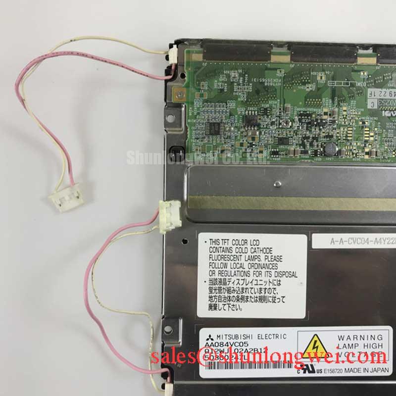
Identify the backlight architecture before applying any replacement drive signal. The available AA084VC07 information does not confirm CCFL, LED, inverter requirements, lamp voltage, lamp current, PWM input behavior, dimming range, or half life. The system integrator should verify the required backlight supply and control method from the original panel documentation. A display with a similar diagonal size may use a completely different backlight interface.
If the installed unit uses a high voltage lamp circuit, keep the inverter, lamp wiring, connector insulation, and secondary return path within the limits specified by the original equipment design. A measured ignition potential such as 1500 to 1650 Vrms cannot be assigned to AA084VC07 without a verified source. High voltage testing should be carried out only with suitable isolation, rated probes, controlled access, and a documented discharge procedure. A continuity check alone does not validate insulation performance under operating conditions.
If the system uses an LED backlight, evaluate the constant current driver, enable signal, dimming command, thermal behavior, and fault response as a complete subsystem. A claimed 1000:1 PWM dimming ratio or a 50,000 hour life figure requires a manufacturer data source and defined test conditions. Neither value should be presented as an AA084VC07 specification from the information available here. Brightness variation across the panel should be checked after the enclosure, front window, and thermal path are installed.
Acoustic noise from an inverter, visible flicker, intermittent brightness, or a delayed backlight may originate in the driver, wiring, grounding, or control signal. Capture the backlight command and supply behavior while comparing the original and replacement assemblies. For high EMI environments, route display and backlight wiring according to the equipment grounding and shielding plan, then verify the finished console under its actual switching loads. The LCD module itself should not be represented as independently certified for whole equipment EMC compliance.
⚠ Safety Interlock Note: Disconnect power and allow the backlight circuit to discharge before removing display cables or probing the inverter side of the assembly.