

Content last revised on October 5, 2026
Industrial Bezel Mechanical Envelope Tolerances and Mounting Stress
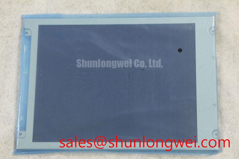
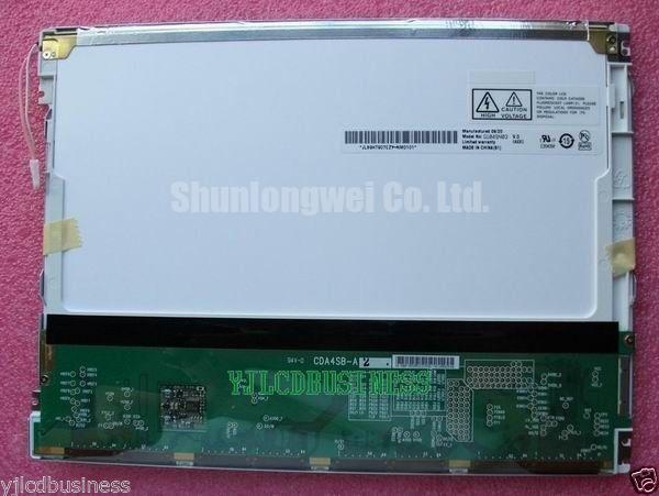
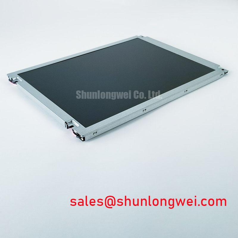
Inspect the bezel and connector area of the AA104VC10 before applying power, recording any frame distortion, damaged contacts, or uneven seating against the original equipment mounting points. This Mitsubishi Electric part is identified as an industrial grade TFT LCD display module for HMI use. Its identification alone does not establish the active area, resolution, interface pinout, supply requirements, or backlight drive method; those details must be checked against the original panel documentation before installation.
Begin a replacement assessment with the surfaces that actually locate the display. Compare the original panel and the AA104VC10 for overall frame clearance, mounting point position, connector access, and the space available for the cable after the enclosure closes. A panel that fits the visible opening can still load the frame unevenly when its mounting points meet a different bracket geometry. With the display unpowered, place it in the chassis without drawing it into position with the screws. Check whether it rests flat and whether a cable or enclosure feature pushes against its rear surface.
Mounting stress deserves an optical check, not just a mechanical one. After assembly, show a uniform dark image and then a uniform midtone image. Note any bright or dark patches that appear near mounting points, and compare them with the same images before the enclosure was tightened. Such changes can indicate pressure on the display assembly, but they do not identify a particular internal layer as the cause. If the equipment manufacturer specifies a tightening sequence or torque, use that instruction; no AA104VC10 fastener torque or bezel tolerance is established by the supplied product identification.
For procurement, retain photographs of the original label, frame, mounting points, and cable exit. Those records make a dimensional comparison more useful than a shared product category. The AA084VC01 is another panel that can be reviewed during an alternative part assessment, but it should not be treated as a direct replacement without confirming its drawing, electrical interface, optical requirements, and enclosure fit against the AA104VC10 installation.
Backlight Startup, Brightness Uniformity and Driver Checks
Do not connect a backlight driver on the basis of panel size or a similar looking connector. The system integrator should verify the AA104VC10 backlight type, connector assignment, and required drive conditions from the original panel documentation. In particular, an inverter intended for a high voltage lamp and a constant current LED driver are not interchangeable test supplies. Neither a lamp ignition voltage nor an LED current rating is established by the supplied product information, so applying a presumed value would turn an incoming inspection into an avoidable electrical risk.
On a documented test fixture, observe the image and illumination as separate functions. If the screen appears dark, first verify the host’s display signal and the backlight supply at the appropriate test points using the equipment service information. A faint image visible under external light can help direct attention toward illumination, while a lit screen without a valid image calls for a signal and power sequencing check. Neither observation proves a single failed part. Record whether the symptom occurs only at startup, after warming, or when brightness is adjusted, and compare the behavior with a known good signal path where available.
For brightness and color temperature assessment, use the same displayed image, viewing position, and measurement conditions for each panel being compared. A full white field can reveal broad illumination differences; a neutral gray field often makes patches or tint changes easier to document. Photographing both screens with independently adjusted camera exposure can conceal a real difference, so lock the camera settings or use a suitable optical instrument. If a procurement requirement specifies a minimum brightness or an allowable uniformity range, judge the result against that requirement rather than an assumed AA104VC10 factory figure. No backlight lifetime or brightness decay rating is established here.
Brightness control also belongs in the system check. If a display appears to flicker or produce audible noise during dimming, examine the host control signal and its driver documentation before changing settings. Dimming behavior depends on the installed driver and its control method; no PWM frequency, duty cycle limit, or dimming ratio can be assigned to the AA104VC10 from its model identification alone.
Cable Seating, Signal Integrity and Power Sequencing
Inspect the mating cable under good light before connecting the panel. Look for a straight contact edge, intact reinforcement, clean contacts, and a bend path that will not be pinched when the enclosure closes. Align the cable squarely with the connector, engage any latch as intended, and then check that both sides remain level. A cable seated at an angle may work during an open chassis test yet lose contact after the assembly is moved. Avoid repeatedly flexing an existing cable at the same point during troubleshooting; its service condition cannot be inferred from how many insertions it has survived.
💡 Bench Tip: Disconnect power and use ESD protection before handling the panel connector, then confirm that the cable is fully seated and any latch is evenly closed.
If horizontal bands, unstable pixels, or intermittent color appear, document whether the pattern changes when the equipment operates nearby motors or when the cable is repositioned without straining it. Check connector seating and grounding continuity against the host design, then compare the display signal with a known good path using suitable instruments. Electrical noise may be relevant in an enclosure containing a variable frequency drive, but it is not proof that shielding or a ferrite is missing. Cable shielding, termination, and routing must follow the actual host interface and be validated in the assembled equipment; the AA104VC10 interface and connector shell construction have not been specified here.
A white screen or an image that persists briefly during shutdown also calls for a sequencing review. Use the equipment schematic and original panel documentation to verify the order in which panel power, image data, and backlight control are applied and removed. Observe the rails and enable signals through startup and shutdown rather than changing delays by trial and error. An apparently uniform white field can result from more than one fault, including a missing image signal or an incorrectly seated connection. For broader HMI troubleshooting context, Industrial Display & HMI Solutions discusses system level considerations; the host documentation remains the authority for this panel’s connections.
Optical Screening for Lines, Shadows and Persistent Images
Run a repeatable full screen color check after the panel is mounted and the signal path is stable. Display red, green, and blue fields in turn, then add white, black, and gray fields to distinguish isolated pixel defects from broader nonuniformity. Record each observation by screen position and photograph it with consistent exposure. A line that remains in the same location across all color fields deserves a different investigation from a shadow visible mainly on dark or gray content, but the pattern alone does not establish a damaged internal connection.
For a dark area, compare the powered image with the unpowered surface under a flashlight held at an oblique angle. This can help reveal surface marks, reflections, or enclosure shadows that might otherwise be mistaken for a display defect. Repeat the powered test with the enclosure open if the service procedure permits it. If the appearance changes, inspect mounting pressure and surrounding parts before assigning a cause to the glass or electronics. Do not press on the active area to reproduce an intermittent line; check the cable and the host signal path without loading the display surface.
A mining shovel or earthmoving equipment telematics display is one possible integration assessment, not an established AA104VC10 application rating. For that use, compare the panel’s documented optical and environmental limits with the cab enclosure, ambient light, vibration control, and operator viewing position. Sunlight readability, anti glare treatment, and contrast under bright ambient light cannot be verified from the supplied identification. Test those requirements in the intended assembly instead of relying on an indoor bench image.
If an HMI presents static icons or status bars for long periods, include an image retention check in the equipment qualification plan. Show a uniform field after the normal operating display and record whether a residual pattern is visible, how it changes, and the conditions under which it was observed. This observation should be kept separate from permanently fixed lines and from backlight nonuniformity. Any mitigation through interface layout or display operation belongs to the system design and should be evaluated against the original equipment requirements.