Content last revised on October 2, 2026
Assembly Integrity & Layout Architecture: Implementing High-Speed Fault Management for BSM100GAL120D
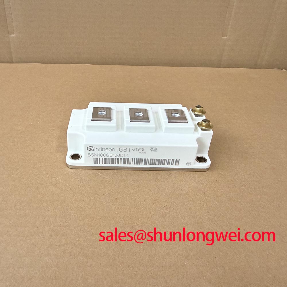
Before energizing a replacement, inspect the BSM100GAL120D module for housing damage, verify the nameplate ratings, and compare cold-state terminal behavior with a known-good unit from the same inverter assembly. The documented device identity is an Infineon IGBT module rated at 1200.0 V and 100.0 A, with a module-style package. These are official product parameters; switching frequency, gate-drive requirements, thermal resistance, short-circuit withstand time, isolation rating, and terminal assignment should be confirmed from the applicable manufacturer documentation before commissioning.
| Parameter | Official Product Information |
|---|---|
| Manufacturer | Infineon |
| Part number | BSM100GAL120D |
| Product category | IGBT Module |
| Rated voltage | 1200.0 V |
| Rated current | 100.0 A |
| Package | Module |
When this module is evaluated in a commercial string inverter or micro-grid energy-storage converter, the first practical task is to separate the device rating from the protection capability of the complete power stage. The 1200.0 V rating and 100.0 A rating identify the component boundary; they do not establish an approved DC-link voltage, overload profile, switching condition, or short-circuit duration for a finished converter.
A desaturation protection circuit may be considered as part of the gate-driver architecture, but the required detection time, blanking interval, fault threshold, and soft turn-off sequence must be established from the selected driver, module data, bus inductance, and measured switching waveform. The requested sub-microsecond or microsecond-class protection targets are not official parameters provided here and must not be treated as guaranteed characteristics of this module. Designers should verify the complete protection response under controlled short-circuit testing while monitoring collector-emitter voltage, gate voltage, current, and turn-off overshoot.
Minimize the high-current commutation loop and keep the gate-drive return path separate from power-current paths. If the original schematic identifies an auxiliary emitter or sense return, route it according to that documented terminal function rather than assuming that every module terminal provides a Kelvin connection. Long motor or inverter output cables can produce reflected-wave voltage stress; the appropriate filter, damping network, cable arrangement, and switching edge control remain system decisions validated with an oscilloscope at the module terminals.
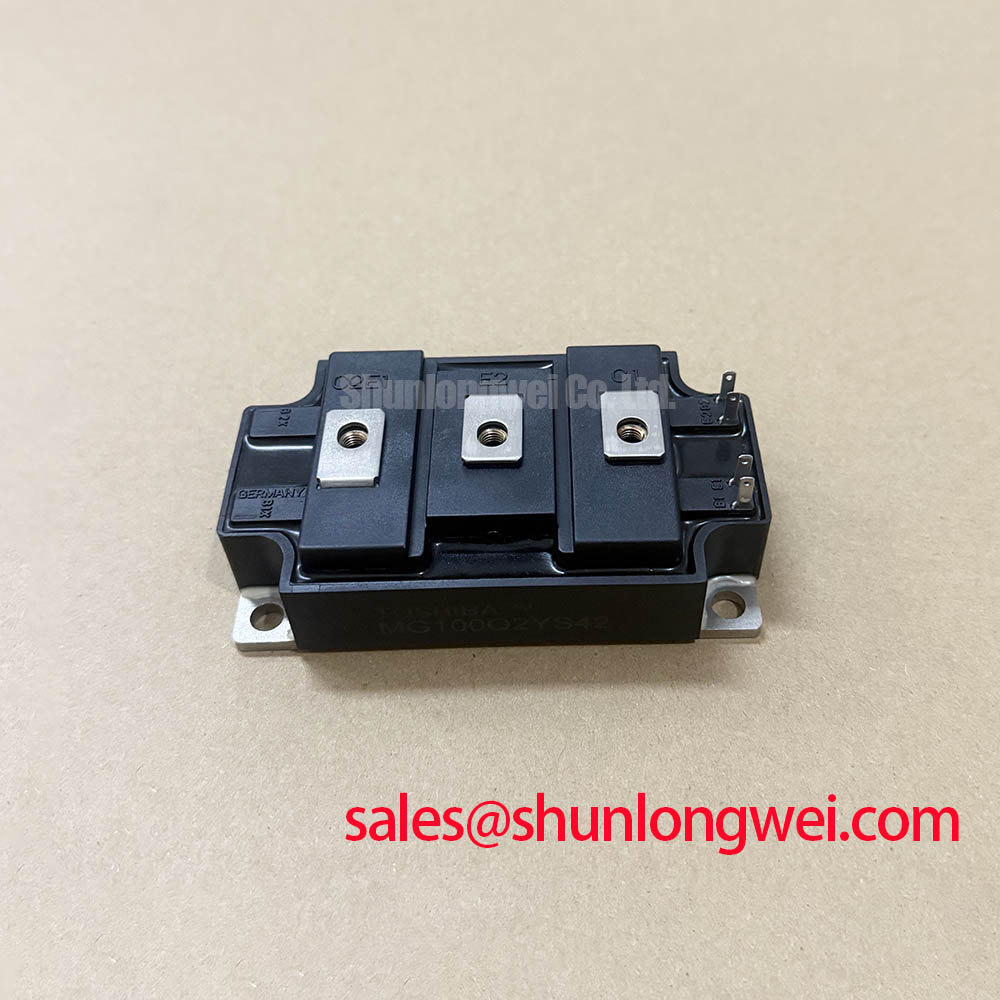
For a repair comparison, the FS100R12N2T4 may be reviewed as a separate Infineon reference device, but voltage, current, pin assignment, mechanical envelope, thermal interface, and gate characteristics must be matched independently before any substitution is considered.
Preventing Spurious Faults: Galvanic Gate Drive Isolation and Parallel-Module Review
Check the gate-driver isolation barrier, creepage and clearance arrangement, isolated power supply, shield termination, and control-ground reference before applying a replacement module. Reinforced isolation above a stated voltage and common-mode transient immunity above a stated slew rate cannot be assigned to the BSM100GAL120D without the relevant driver and system documentation. Those values belong to the gate-driver and converter insulation design, not automatically to the IGBT module.
During bench testing, compare the gate-emitter waveform at the module terminals with the driver output measured at the isolated side. Unexpected gate movement may result from common-source inductance, capacitive coupling, an unstable isolated supply, probe-ground errors, or an incorrect return path. Verify the signal against a known-good phase leg and use measurement equipment suitable for the converter’s common-mode voltage.
Parallel operation requires special care. Static current sharing depends on electrical symmetry, semiconductor characteristics, thermal coupling, busbar geometry, gate-loop impedance, and dynamic switching behavior. A positive temperature coefficient of on-state voltage can support current sharing in some operating regions, but it is not a substitute for matched layout and measured validation. Keep corresponding power paths physically symmetrical and confirm current balance during startup, steady operation, and fault interruption.
In a front-end or complementary converter topology, engineers may assess the BSM75GD120DLC as a separate device within the surrounding power chain. It should be treated as an independent evaluation item; rectifier function, control timing, voltage stress, and thermal requirements must be checked against the actual system schematic.
Benchtop Waveform Tuning: Managing Switching Stress and Environmental Uncertainty
Use a differential high-voltage probe and a properly rated current measurement method to inspect collector-emitter overshoot during turn-on and turn-off. The measured peak should be compared with the DC-link operating condition and the module’s documented electrical limits. Reduce parasitic loop inductance as a layout principle, then allow the system engineer to determine whether snubbers, active gate control, ferrite elements, or output filtering are appropriate after waveform evidence is collected.
Long cable runs deserve a separate test condition because impedance mismatch and reflected waves can raise local voltage peaks at the inverter output or motor terminals. Do not infer cable-related stress from a low-voltage bench result. Test the actual cable length, termination, motor or load impedance, and switching pattern, then verify the waveform at the power module and load interface.
Altitude, terrestrial neutron exposure, cosmic-ray effects, Single Event Burnout, FIT rate, and voltage derating require validated reliability data and an application-specific model. No such source data is established here, so a definite burnout probability, altitude multiplier, operating-life figure, or required voltage headroom must not be assigned to this product page. As a design consideration, engineers evaluating installations above normal reference conditions should obtain the manufacturer’s reliability guidance and verify the DC-link stress through environmental and switching tests.
The Ultimate IGBT Knowledge Base can provide broader engineering context, while the Infineon IGBT Modules & Discretes Official Portfolio remains the appropriate manufacturer-level reference for product-family information. Neither reference should be used to infer an unlisted rating for this specific part.
Field Diagnostics & Commissioning: Heatsink Contact and Power-Stage Verification
After electrical screening, inspect the mounting surface, module base, fastener seating, thermal interface coverage, and heatsink flatness. The interface material should be applied as a uniform, controlled layer suited to the approved thermal design; its thickness, allowable voiding, and any baseplate compensation method must follow the module documentation and the system’s thermal calculation. Do not use a visually thick layer as evidence of improved cooling.
Mounting should proceed with the fastener sequence and torque specified for the actual hardware, heatsink, and module assembly. Recheck that the module is not being forced into alignment by busbars or rigid cable lugs. Mechanical stress can alter thermal contact and may also transfer unwanted force to power terminals. After assembly, confirm electrical isolation, terminal tightness, gate-drive continuity, and the absence of unintended conductive paths before connecting the DC link.
⚠️ Field Alert: Disconnect and properly discharge the converter before inserting, removing, or probing module wiring, and never substitute a mounting torque value without confirming the fastener and assembly specification.
For commissioning, begin with controlled low-energy testing where the system architecture permits it, then capture gate voltage, collector-emitter voltage, phase current, heatsink temperature, and fault timing. A mismatch between phases may indicate a wiring, driver, busbar, sensor, or mechanical issue; compare each measurement with the original schematic and a known-good phase rather than assigning a single cause from one symptom. The Infineon EasyPACK™ portfolio is a separate manufacturer reference and should not be treated as a direct mechanical or electrical replacement for this module.