
Content last revised on September 10, 2026
Thermal Stress Alleviation in Bidirectional PCS Power Stages under Daily Cycling
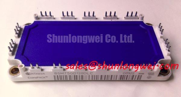
Commercial and industrial battery energy storage system (BESS) power conversion systems (PCS) operate under demanding load profiles. Unlike unidirectional drive inverters that follow predictable operational envelopes, a bidirectional PCS transitions continuously between charging (rectification) and discharging (inversion). During heavy peak-shaving cycles operating between 0.5C and 1C discharge rates, the power semiconductors experience severe cyclic thermal swings. Within this operating topology, the BSM75GD120DLC six-pack IGBT module handles continuous four-quadrant active and reactive power flow between the high-voltage battery rack and the three-phase AC distribution stage.
Thermal fatigue in power modules is driven primarily by the differential coefficient of thermal expansion (CTE) between the silicon chip, the direct copper bonded (DCB) ceramic substrate, and the copper baseplate. When a PCS shifts rapidly from full-load charging to full-load discharging, the junction temperature ($T_j$) undergoes rapid temperature excursions ($Delta T_j$). Rated at a collector-emitter voltage of 1200V and a continuous DC collector current of 75A at a case temperature of 80°C (Official Datasheet Specification), the BSM75GD120DLC exhibits a low saturation voltage of typical 1.70V at $I_C = 75text{A}$ and $T_{vj} = 125^circtext{C}$ (Official Datasheet Specification). This low conduction loss profile helps limit core losses during heavy current throughput, directly suppressing junction peak temperatures.
| Parameter | Official Datasheet Specification | Engineering Assessment Context |
|---|---|---|
| Collector-Emitter Voltage ($V_{CES}$) | 1200V | Ensures DC bus operational margin up to 750V–800V in 400V/480V AC PCS systems |
| Continuous DC Collector Current ($I_C$) | 75A ($T_C = 80^circtext{C}$) | Nominal power throughput for medium-scale 30kW–45kW modular PCS sub-units |
| Repetitive Peak Collector Current ($I_{CP}$) | 150A | Sub-cycle grid-fault transient ride-through and short-duration surge allowance |
| Saturation Voltage ($V_{CE(sat)}$) | 1.70V (Typical, $T_{vj}=125^circtext{C}$) | Directly governs steady-state conduction loss during sustained battery discharge |
| Total Power Dissipation ($P_{tot}$) | 355W (per switch, $T_C = 25^circtext{C}$) | Defines upper thermal dissipation limit into the heatsink structure |
| Short Circuit Withstand Time ($t_{psc}$) | 10 µs ($V_{GE} = 15text{V}$, $T_{vj} le 125^circtext{C}$) | Window for desaturation detection circuitry to suppress DC-link flashover |
| Isolation Test Voltage | 2.5 kV AC (1 min) | Chassis-to-power terminal electrical safety isolation rating |
In plant environments, repetitive thermal cycling causes progressive microscopic degradation at the wire bond interfaces and the substrate solder layer. For systems scaling toward higher capacity racks where current requirements exceed standard 75A thresholds, the related FF150R12ME3G provides a 150A rating in a dual-pack configuration, allowing engineers to balance modular parallel scaling against physical enclosure boundaries. When managing phase-controlled rectification angles in grid-tied operation, harmonic currents can increase conduction losses across specific bridge arms. Maintaining symmetrical switching patterns and precise carrier frequency modulation (typically 4 kHz to 8 kHz for modules in this class) prevents localized hotspot formation across the six internal IGBT switches.
Negative Gate Bias vs Active Miller Clamping in Fast-Switching Half-Bridges
High-efficiency PCS bridge legs switch under rapid voltage transitions ($dv/dt$), creating significant displacement currents through the internal parasitic gate-collector Miller capacitance ($C_{gc}$). When the lower switch turns off and the complementary upper switch turns on, the rising collector-emitter voltage induces a current into the lower switch's gate terminal. Without proper gate circuit conditioning, this induced current creates a voltage rise across the external gate resistance that can exceed the turn-on threshold voltage, causing catastrophic half-bridge shoot-through.
To eliminate shoot-through risks in the BSM75GD120DLC, driver stage architectures must implement either a dedicated negative gate bias (typically $-5text{V}$ to $-8text{V}$) or an Active Miller Clamp. With a total gate charge of 0.70 µC (Official Datasheet Specification), controlling gate transitions requires balanced drive impedance. An Active Miller Clamp monitors the gate voltage during the turn-off phase. Once $V_{GE}$ drops below a set threshold (typically around 2.0V), a low-impedance internal MOSFET connects the gate directly to the emitter rail, shunting induced Miller currents away from the primary gate resistor.
High-voltage bridge legs also require protective coordination between semiconductor-grade high-speed fuses and the module short-circuit withstand rating. The BSM75GD120DLC provides a certified short-circuit withstand time of 10 µs under $V_{GE} = 15text{V}$ and nominal bus conditions (Official Datasheet Specification). Field engineers must verify that the selected DC and AC branch fuse total clearing integral ($I^2t$) operates well beneath the module rupture energy threshold under short-circuit conditions.
Bootstrap gate-driver supply circuits require careful capacitor selection to prevent voltage dropouts during low-frequency inverter states. Electrolytic or ceramic bootstrap storage capacitors must supply sufficient continuous charge to sustain gate voltage throughout maximum duty cycles, while the associated high-voltage bootstrap freewheeling diode must have an ultra-fast reverse recovery characteristic to prevent high-voltage injection back into the low-voltage logic rail. For comprehensive diagnostic techniques on gate driver isolation, dynamic switching ringing, and failure analysis procedures, consult the technical guidelines in the Field Engineer’s Handbook.
Thermal Interface Material (TIM) Thickness Uniformity and Void Minimization
Baseplate heat dissipation is the single most critical factor determining operating life in sealed, outdoor industrial PCS enclosures. The copper baseplate of the BSM75GD120DLC relies on direct metallic contact with an extruded or liquid-cooled heatsink to transfer internal losses. Because mechanical contact surfaces have microscopic surface roughness and mechanical tolerances, un-filled air pockets create high thermal resistance barriers.
Applying Thermal Interface Material (TIM) requires precise control over layer thickness. A dry or unevenly applied thermal compound layer will lead to junction overheating, while excessive paste thickness increases thermal resistance ($R_{th(c-s)}$). A wet-film thickness between 50 µm and 100 µm (General Industry Design Consideration for standard power modules) ensures complete air displacement without creating an excessively thick thermal barrier.
⚠️ Maintenance Note: In operational facilities, thermal paste degradation is a leading cause of unscheduled inverter tripping. Over 3 to 5 years of daily thermal cycling, lower-grade silicone-based thermal greases can suffer from "pump-out" effects and solvent evaporation, leaving chalky, void-filled residues beneath the central module area. Inspect module-to-heatsink delta temperatures during regular facility shutdowns. If the temperature differential between the module baseplate and the adjacent heatsink fin exceeds 15°C under nominal load, clean the baseplate and re-apply fresh, non-curing synthetic TIM.
Proper mechanical installation prevents mechanical deformation of the internal ceramic DBC substrate. Mounting torque must follow a standardized cross-pattern sequence to ensure uniform pressure distribution across the baseplate:
- Pre-fastening: Fasten all M5 mounting bolts diagonally to a snug contact torque of approximately 0.5 N·m to 1.0 N·m (Design Consideration).
- Final Torque: Progressively torque all fasteners to the final specified mounting torque of 2.5 N·m to 3.5 N·m (General Industry Design Consideration for standard M5 baseplate fixings).
- Surface Flatness: Ensure the heatsink mounting area has a surface flatness tolerance of $le 50,mutext{m}$ over a 100 mm span with a surface roughness ($R_z$) of $le 10,mutext{m}$.
For large-scale utility installations requiring unified power blocks with integrated baseplate architectures, designers frequently examine high-integration formats such as Infineon EconoPACK™ Plus to streamline modular assembly lines.
Evaluating Thermal Capacitance vs Heat Sink Time Constant under Surge Bursts
During grid fault ride-through (FRT) events, reactive power compensation pulses, or high C-rate battery surge loads, the PCS power semiconductors encounter brief overcurrent conditions up to the module peak rating of 150A (Official Datasheet Specification). In these short-duration bursts lasting from a few milliseconds to several seconds, the physical thermal mass of the bulk heatsink is too distant to absorb the immediate thermal wave. The junction temperature profile is governed entirely by the transient thermal impedance ($Z_{th(j-c)}$) of the silicon chip and internal DBC ceramic assembly.
The transient thermal behavior of the module can be analyzed using multi-element RC network models (Foster or Cauer representations). The silicon chip itself possesses a very small thermal capacitance, responding to heat flux within milliseconds, while the copper baseplate features a thermal time constant in the range of several hundred milliseconds. In contrast, the extruded aluminum heatsink typically responds on a time constant scale of 60 to 180 seconds. During a 200 ms grid-support surge burst, heat remains largely trapped within the module packaging layers, making dynamic calculations of peak $T_j$ margins essential for system protection settings.
💡 Pro Tip: In outdoor containerized BESS enclosures, rapid ambient temperature drops combined with high industrial humidity can create internal condensation on cold heatsink fins during inverter idle periods. Always configure PCS enclosure climate controllers to maintain interior air temperatures above the local dew point, and verify that the 2.5 kV AC isolation barrier (Official Datasheet Specification) is fully protected from moisture ingress across terminal creepage paths.
For auxiliary systems, small pump drivers, and cooling subsystem control stages within the PCS container, compact integrated solutions like Infineon CIPOS™ Nano IPM Series provide compact footprints that complement the main primary power bridge.