

Content last revised on September 10, 2026
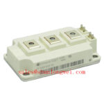
FF150R12ME3G Infineon EconoDUAL™ 3 IGBT Module | 1200V 150A Power Switching
The Infineon FF150R12ME3G half-bridge module optimizes switching efficiency and thermal performance in heavy-duty industrial environments. Providing a robust rating of 1200V, 150A, and an extremely low junction-to-case thermal resistance of 0.18 K/W, it represents a benchmark for low-loss power switching. Engineers looking to minimize thermal dissipation can rely on its integrated NTC thermistor for real-time temperature tracking. For industrial motor drives prioritizing switching efficiency and baseplate isolation, this 1200V EconoDUAL 3 module is the optimal choice.
Key Parameter Overview
Decoding the Specs for Enhanced Thermal Reliability
| Maximum Rated Values | ||
|---|---|---|
| Collector-emitter voltage | VCES (Tvj = 25°C) | 1200V |
| Continuous DC collector current | IC nom (TC = 80°C) | 150A |
| Continuous DC collector current | IC (TC = 25°C) | 200A |
| Repetitive peak collector current | ICRM (tP = 1 ms) | 300A |
| Total power dissipation | Ptot (TC = 25°C, Tvj max = 150°C) | 695W |
| IGBT Characteristic Values | ||
| Collector-emitter saturation voltage | VCE(sat) (IC = 150A, VGE = 15V, Tvj = 25°C) | 1.70 V (typ) / 2.15 V (max) |
| Collector-emitter saturation voltage | VCE(sat) (IC = 150A, VGE = 15V, Tvj = 125°C) | 2.00 V (typ) |
| Thermal resistance, junction to case | RthJC (per IGBT) | 0.18 K/W (max) |
| Diode Characteristic Values | ||
| Forward voltage | VF (IF = 150A, VGE = 0V, Tvj = 25°C) | 1.65 V (typ) / 2.15 V (max) |
| Thermal resistance, junction to case | RthJC (per Diode) | 0.34 K/W (max) |
| I²t-value | I²t (VR = 0V, tp = 10 ms, Tvj = 125°C) | 4600 A²s |
| Module Properties | ||
| Isolation test voltage | VISOL (RMS, f = 50 Hz, t = 1 min) | 2.5 kV |
| Internal isolation | Al2O3 basic insulation | Class 1 (IEC 61140) |
| Creepage distance | Terminal to heatsink | 14.5 mm |
| Clearance distance | Terminal to terminal | 13.0 mm |
| Rated NTC resistance | R25 (TC = 25°C) | 5.00 kΩ |
Download the FF150R12ME3G datasheet for detailed specifications and performance curves.
Application Scenarios & Value
Achieving System-Level Benefits in High-Power Conversion
Engineers designing industrial frequency converters often encounter thermal management challenges. In high-power variable frequency drives (VFDs) and ventilation systems, high starting currents stress power modules. The FF150R12ME3G provides a nominal collector current of 150A at 80°C to handle these continuous loads reliably. Its EconoDUAL™ 3 footprint integrates the half-bridge layout within a standardized housing. This simplifies mechanical packaging and standardizes copper busbar integration.
For systems with inductive loads, voltage spikes can compromise silicon integrity. The module's built-in diode exhibits a low forward voltage of 1.65 V and a 4600 A²s current rating. These attributes safeguard the inverter structure from high-energy reverse transients. While this module fits standard industrial drives, designs requiring alternative switching profiles may evaluate the related FF150R12KE3G or FF150R12RT4.
Technical & Design Deep Dive
A Closer Look at the Trenchstop Technology and Dual Configuration
The module leverages trench gate geometry to combat the trade-off between switching speed and conduction losses. Let us explain this with an analogy: planar gates behave like narrow country roads where charge carriers must slow down at tight bottlenecks, causing high electrical resistance. In contrast, the trench structure acts like a multi-lane highway system, routing charge carriers vertically through the silicon and lowering the saturation voltage to a typical 1.70 V at 25°C. For engineers designing high-efficiency power stages, understanding the internal construction of these devices is crucial; a helpful starting point is this in-depth analysis of IGBT modules.
To ensure grid compliance and protect adjacent low-voltage control circuitry, the module boasts a robust 2.5 kV isolation test voltage. The high clearance distance of 13.0 mm and creepage distance of 14.5 mm act like physical safety firebreaks on a high-voltage PCB. They prevent surface arcing and current leakage even in harsh, dusty, or humid operating environments.
What is the primary benefit of the trenchstop technology? It minimizes conduction losses by lowering saturation voltage. How does the integrated thermistor protect the module? It monitors junction temperatures to prevent thermal runaway. To prevent overvoltage peaks or gate oscillations, proper IGBT gate drive design is essential. The module utilizes the robust Infineon TRENCHSTOP™ IGBT3 platform to ensure reliable performance under repetitive loads.
Frequently Asked Questions
Addressing Critical Engineering Design Questions
How does the low collector-emitter saturation voltage (VCE(sat)) of typical 1.70 V impact energy dissipation in continuous duty cycles?
The low saturation voltage directly reduces conduction losses. At 150A, a VCE(sat) of 1.70 V minimizes thermal stress on the junction during high-duty continuous operation, reducing the size of the required heatsink.
Can the integrated NTC thermistor be used directly for overtemperature protection control loops?
Yes, the built-in NTC thermistor offers a nominal resistance of 5.00 kΩ at 25°C. It provides accurate, localized temperature feedback directly from the module's substrate, enabling active thermal monitoring to prevent thermal runaway.
For detailed pricing, availability, and official technical support on this and other power semiconductors, contact our sales engineering team today to review your system requirements.


